Measuring systems and thermal mass flow modules are mostly offered in a broad range of products by few suppliers in the market. Majority of these designs are ready-to-use compact systems with an outlet and an inlet and a channel having a passive or active output.
These modules are enough for a number of general purpose applications where component size and price are less significant but are not needed for limited-space and price-sensitive flow control solutions. In certain instances IST thermal flow sensor elements offering considerable solutions.
The most popular anemometer is the constant temperature anemometer (CTA). Its function is described with King’s Law

On simplifying and converting the equation the following is obtained:
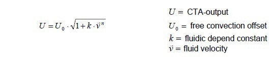
Here, U0 shows the value of constant temperature difference ( ΔT ) between the heater and fluid. In a strict sense, the resistive structure is kept at a constant temperature by the CTA controller.
So, different passivation thicknesses and flow element surfaces effect the CTA characteristics, even a deviation in the heat transfer coefficient (α). The characteristics are based not only on sensor alignment/orientation and fluid type, but also on sensor contamination such as dust and fluid temperature.
The equation of a still fluid is:
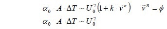
That implies that each deviation of CTA-characteristic, caused by free convective parameters like α0 can be compensated by a U0 -adjustment at ν=0. For calibrating the k -value (fluidic-caused errors) more than one point is essential. However, fluidic-caused errors are mostly based on mechanical alignment deviations of the sensor mounting. If mounting errors can be determined by module construction, a single point calibration offers good results for a number of applications.
Circuit
The schematic below shows a simple feedback circuit for temperature regulation of flow sensors heater. The temperature sensor Pt1200 on chip compensates the medium temperature variation.
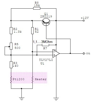
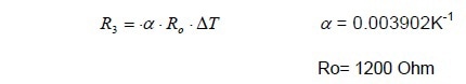
For each case it is essential to perform tests for determining the best resistor selection for the flow sensor. For gas applications, a medium temperature difference of about 30K on the heater is recommended. For liquids, a medium temperature difference in the order of 10K will be enough. Using this temperature difference, R3 is determined by the following equation:
With R5 and a short circuit at R3, the bridge can be balanced at flow = 0. The output of U1 will be adjusted to a minimum value. On replacement of the R3 short circuit, the output reaches to its offset voltage depending on free heat convection from sensor to medium.
Te R7 resistor is placed for stability of anemometer circuit. Depending on used OpAmp it will be valued from 1,1 to 3Mohms. The OpAmp should be a low input bias current type.
Designing Flow Channel
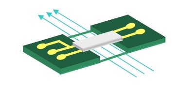
With reference to the above image using a flow channel for a high-performance flow measurement it is essential to have a laminar flow profile passing the sensor. Certain parameters must be calculated.
The picture shows the flow profile development across a flat plate.
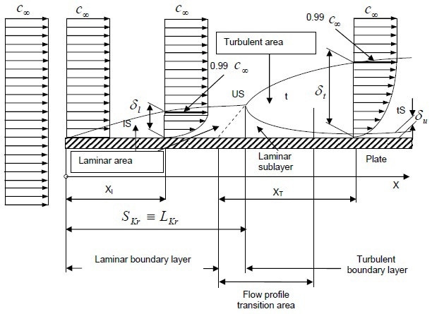
Here a specific distance Xl from the leading edge S is required to have nearly a fully developed laminar flow profile. This is the needed position of flow sensor behind the leading edge S where the flow meets the plate. The value δl shows the thickness of laminar boundary layer at distance Xl from leading edge S.
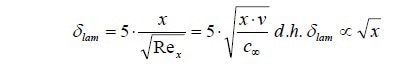
That is also the minimum deepness of flow channel. Along with Reynolds Number (Re), and based on the flow velocity and Re(critical) < 300000 a PCB flow channel can be calculated.
c= flow velocity,
x= distance ,
ρ = density,
μ = dynamic viscosity
Example: sensor position 30mm behind leading edge, flow velocity 10m/s, medium = air
Solution: Minimum depth of channel = 1mm

This information has been sourced, reviewed and adapted from materials provided by Innovative Sensor Technology.
For more information on this source, please visit Innovative Sensor Technology.