The thermal conductivity of air is of the order 0.02 Wm-1K-1, meaning even slight air gaps can produce substantial thermal resistances. In contrast, the thermal conductivity of a plastic or thermal paste is of the order 0.2 Wm-1K-1. Hence, thermal resistance is lower than air by a factor of 10 for the same thickness. Using heat flux sensors it is essential to fill up any air gaps, as these significantly increase thermal resistance.
For example, a 0.05 x 10⁻³ m air gap has a thermal resistance of 20 x 10-4 KW-1m2, compared to 11 x 10-4 KW-1m2 for Hukseflux’s FHF05 series or 70 x 10-4 KW-1m2 for HFP01. This represents an increase in thermal resistance of 200 % and about 30 % compared with FHF and HFP01, respectively.
By utilizing a filler of 0.05 x 10⁻³ m with a thermal conductivity about 10 times higher than that of air, the thermal resistance can be reduced to 2.5 x 10⁻⁴ KW-1m2, corresponding to only a 20 % and 3 % increase compared with FHF and HFP01 respectively.
From this example you can also see that it is not necessary to use high-thermal conductivity tapes. Instead, using a thin, standard tape is sufficient.
Air gaps lead to higher thermal resistance for conductive heat, but also to changes to radiation balance. A sensor with an air gap below it is a “resistance” (a radiation screen) for radiative transfer, and if filled-up they no longer provide any resistance for radiative transfer.
In cases where radiative (far infra-red) heat flux is significant, the presence of an air gap can be the dominant source of errors. This is because a sensor with an air gap acts as a radiation shield, reducing local radiative transfer by a theoretical maximum of 50 %.
How to Address Air Gaps when mounting heat flux sensors
To fill up air gaps, tapes, sheet (gasket) material, glues and cements may all be employed.
Gaps may occur due to the nature of the surface, particularly if the surface is not smooth. Hence, it is imperative to smoothen surfaces or fill up holes before installation.
Gaps between sensor and surface can also arise due to surface curvature. For practical purposes, a surface with a radius larger than 5 m is considered “flat”. For surfaces with smaller radii, the use of flexible sensors should be considered. For industrial heat flux sensors such as Hukseflux’s IHF01 and IHF02, coupling pieces with a flat and curved side may also be provided.
The Importance of Optical Properties
In cases where heat flux sensors are mounted at a surface, heat is usually transferred through a combination of convection and radiation. The thermal resistance of the sensor must be minimized to effectively detect convective heat. For radiative heat, the optical surface properties of the sensor must be representative of the surrounding area.
Some important points to consider:
- Radiation extends beyond the visible spectrum to include non-visible far infrared.
- Blank metal surfaces reflect both visible and far infrared radiation.
- Materials such as paints, plastic coatings, wood, and stone absorb radiation differently depending on their color in the visible range. However, in the far infrared range, these materials generally behave similarly and absorb radiation like "black" materials. See Figure 2.
To assess representativeness in the visible and infra red spectral ranges, consider using a combination of normal (visible range) and infrared (far infrared range) cameras.
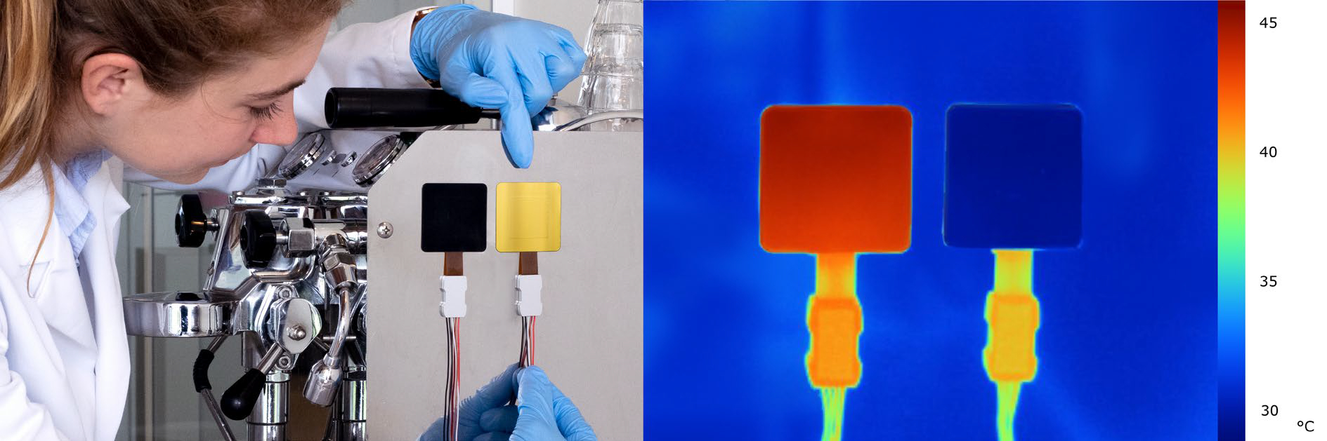
Figure 2. Measuring with BLK – GLD stickers; application of a BLK black sticker and a GLD gold sticker on FHF models for measuring radiative and convective heat flux on an espresso machine. The machine has a polished metal surface of about 45 ˚C. The IR image on the right shows that the black sticker on the left, as well as the sensor wires and connector blocks, emit radiation. They appear in red on the image. The gold sticker and the metal surface have lower emissions and appear as “bluish” on the image. Mounted on the same surface, the BLK and GLD stickers have the same temperature. The measurement with the sensor with the GLD sticker is most representative of the heat flux at the polished metal surface, while the sensor with the BLK sticker overestimates the heat flux. Image Credit: Hukseflux Thermal Sensors B.V.

This information has been sourced, reviewed and adapted from materials provided by Hukseflux Thermal Sensors B.V.
If you would like to have more information about heat flux measurements and heat flux sensors, please contact Hukseflux.