Polynomial compensation determines the pressure values from the signals of pressure and temperature sensors. The ceramic measurement cell for low pressure ranges with the µP electronics of the digital Series 30 transmitter is combined in the new transmitter series, Series 41 introduced by Keller. It is also possible to display and store the values on a PC via an RS485 interface and programming is also possible using the PROG30 software.
The transmitters are calibrated to the base range. The analogue output signal in each section of the range within the base range can be programmed using the PROG30 software.
The KELLER RS converters K-100 Series includes up to 128 transmitters integrated into a bus system and can be read using a PC or laptop. The current pressure of each transmitter or the pressure activity of several transmitters can be recorded or stored while on-line is possible by using READ30 software.
Series 41X Ei is the intrinsically safe version of the pressure transmitter. It is used in explosion exposed areas, where the categories 1 and 2 are required.
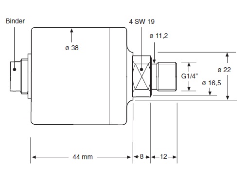
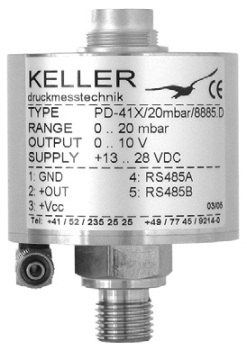
Table 1. Details of the electrical connections.
| Output |
Function |
Binder 723 |
DIN 43650 |
MIL C-264882 |
Lumberg M12 |
Cable |
| 4…20 mA |
OUT/GND |
1 |
1 |
C |
1 |
white |
| 2 Wire |
+Vcc |
3 |
3 |
A |
3 |
black |
| 0…10 V |
GND |
1 |
1 |
C |
1 |
white |
| 3 Wire |
+OUT |
2 |
2 |
B |
2 |
red |
| |
+Vcc |
3 |
3 |
A |
3 |
black |
| Digital |
RS485A |
4 |
|
D |
4 |
blue |
| |
RS485B |
5 |
|
F |
5 |
yellow |
Specification of the transmitters
The specification of the transmitter series are given in table 2.
Table 2. Specification of transmitter series by Keller UK.
| |
Standard FS Pressure Ranges |
| PR-41 X (relative) PD-41 X (diff.) |
30 100 300 mbar |
| Overpressure |
300 1000 1500 mbar |
| Neg. Overpressure |
30 100 300 mbar |
| |
2-Wire |
3-Wire |
| Supply (UB) 41 X |
8…28 VDC |
13…28 VDC |
| Supply (UB) 41 X Ei |
10…30 VDC |
15…30 VDC |
| Analog Output (scaleable) |
4…20 mA |
0…10 V |
| Load (kO) |
<(UB-UB min..) / 20 mA |
≥ 100 |
| Error Band typ.* |
± 0,1 %FS |
± 0,2 %FS |
| Error Band max.* |
± 0,2 %FS |
± 0,3 %FS |
| Stability |
FS ≥ 100 mbar: ± 0.1 %FS |
FS ≤ 100 mbar: ± 0.1 mbar |
| Operating Temperature |
-20…80 °C |
|
| Compensated Range |
10…50 °C |
|
| Pressure Connection |
G1/4” male, Viton® flat seal |
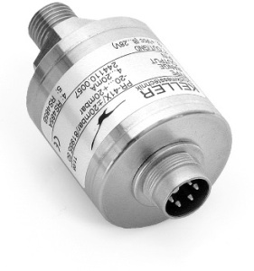
| Electrical Connection |
Binder Series 723 (5 pole) |
| Material in Contact with Media |
Stainless steel (AISI 316L), Nitril O-ring, gold-coated ceramic diaphragm |
| PD-Reference side |
Non-aggressive dry gases |
| Protection / Weight |
IP 40 / ca. 190 g |
| Special Versions |
- IP 67
- Alternative plugs (see front page)
- Cable version
- Pressure ranges neg./pos.: Example: -10…+10 mbar
- Intrinsically safe version for use in explosion exposed areas (must only be used in combination with certified intrinsically safe equipment!) |
PD-41 X Dimensions ø 50 x 62 mm.
All intermediate ranges for the analog output are realizable with no surcharge by spreading the standard ranges. ** Option: Adjustment directly to intermediate ranges (below 20 pieces against surcharge).
For higher pressure ranges and for “wet/wet”-differential applications, KELLER offers Series 33 X resp. Series 39 X.
** Note that the error band will then increase proportionally.
Polynomial Compensation
A mathematical model is used to derive the precise pressure value (P) from the signals measured by the pressure sensor (S) and the temperature sensor (T). The transmitter in the microprocessor uses the following polynomial to calculate P:
P(S,T) = A(T).S0 + B(T).S1 + C(T).S2 + D(T).S3
With the following coefficients A(T)…D(T) depending on the temperature:
A(T) = A0.T0 + A1.T1 + A2.T2 + A3.T3
B(T) = B0.T0 + B1.T1 + B2.T2 + B3.T3
C(T) = C0.T0 + C1.T1 + C2.T2 + C3.T3
D(T) = D0.T0 + D1.T1 + D2.T2 + D3.T3
Various levels of pressure and temperature in the transmitter are factory-tested. The measured values of S along with the exact pressure and temperature values allow the calculation of the coefficients A0...D3. These are written into the EEPROM of the microprocessor.
The microprocessor measures the signals (S) and (T), calculates the coefficients according to the temperature and produces the exact pressure value by solving the P(S,T) equation when the pressure transmitter is in service.
Accessories Series 41 X
The user can make use of the digital interface and the RS485 halfduplex integrated in Series 41 X transmitter. The transmitter is connected via RS232-RS485 converter (i.e. K-102, K-104 or K-107) to a PC or Laptop. Following are the two programs offered:
PROG30: The instrument settings
- The analog output (i.e. different unit, other pressure range) can be reprogrammed.
- Instrument address (for bus-operation) can be set.
- Actual pressure value can be indicated
- Call upon information such as pressure- and temperature range, version of software, etc.
- Units can be selected.
A new zero and gain for the transmitter can be set:
- The switch output can be programmed
- Output rate can be changed.
READ30: Data collection with graphs
- Pressure signals in a graph can be read-out and viewed
- Up to 16 transmitters on one serial connection (Bus-operation)
- Documentation of dynamic measurements
The transmitters can also be tied into the customer’s own software.
Description of the Series
The Intrinsically Safe Capacitive Pressure Transmitters Series 41 X Ei and Series 46 X Ei for Hazardous Applications are shown below.
Description and Application
Both the series are intrinsically safe capacitive pressure transmitters for the conversion of pressure into an electrical signal, for use in hazardous environments requiring equipment of category 1 and 2.
The corresponding data sheet or the agreed specifications gives the characteristics of the pressure transmitter.
Installation
Pressure transmitter with thread connection:
Electrical Connection
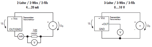
When the transmitters are provided with a plug, it is sufficient if one uses the corresponding seal and counter plug both of which are included in delivery. The guarantee of the plug version protection is by the seal mounted between the counter plug and the plug. Use only screened cable and connect the cable shield.
| Versorgungsstromkreis / Supply Circuit / Circuit d‘alimentation |
Signal- und Schnittstellenkreise zusammen / Signal- and Interface Circuits combined / Circuit de sortie |
| U¡ |
≤ 30 V |
Uo |
≤ 14,7 V |
| I¡ |
≤ 100 mA |
Io |
≤ 464 mA |
| P¡ |
≤ 640 mW |
Po |
≤ 1,71 W |
| C¡ |
0 nF |
– |
– |
| L¡ |
0 mH |
C¡ |
0 nF |
| – |
– |
L¡ |
0 mH |
Only use screened cable and connect the cable shield to the transmitter side. Ensure that the grounding is provided over the cable shielding or the plug should the transmitter grounding not be guaranteed over the pressure connection.
Position Tolerance
The normal purpose position of the capacitive pressure transmitter is with the downward pressure connection. Based on the positional change and pressure range of the transmitter, the zero signal could vary up to ±0.75 %FS because of the self-weight of the ceramic diaphragm.
Service
The pressure transmitters from Keller do not require any maintenance. The recalibration cycle depends on the application conditions. Recommended recalibration cycle is 1 year. The sediments on the ceramic diaphragm could lead to signal changes.
In case this happens, the ceramic diaphragm is carefully cleaned using a soft brush and a commercial lime scale remover. Afterwards, the pressure transmitter is washed with cold water.
Safety Instructions
While installing and operating the pressure transmitters, attention should be paid to the corresponding national safety regulations and to the relative country regulations concerning the Ex-application.
The Series 41 X Ei pressure transmitters need to be mounted onto unpressurized systems. The ceramic diaphragm must be protected against damages.
Special Conditions for Safe Use
For pressure measurements that require category 1 equipment, the capacitive pressure transmitter of the 41 X Ei series must be built into the boundary wall with a tightness at least IP67.
When the capacitive pressure transmitter of the 46 X Ei series is used, the metal casing of the capacitive pressure transmitter must be earthed and care must be taken that the capacitive pressure transmitter cannot swing freely. The cable of the capacitive pressure transmitter of the 46 X Ei series must be led through out of the category 1 range using a cable screw connection (of at least protective category IP67) and externally connected.
The electrical parameters of the respective intrinsically safe device/component may not exceed the values in the table opposite. Permissible ambient temperature: -20...+80 °C.
Marking
About Keller UK
KELLER is Europe's largest manufacturer of isolated piezoresistive pressure sensors and pressure transmitters. KELLER are a world leader in pressure sensing technology continually developing new materials and manufacturing processes, that is why this company remain successful.
This Company introduces a comprehensive range of products, from simple Pressure Capsules, to fully compensated digital pressure transmitters, also low-cost industrial pressure transmitters, digital pressure gauges, recording digital manometers. Modern advanced production techniques enable KELLER to offer competitive pricing for medium and high volume production orders. Customer engineered special products are easily accommodated.
KELLER supply Pressure Sensors to all industries and applications and are specialist in the following areas: Refrigeration, Oil & Gas 'down-hole', Water Depth, Hydraulics, Autoclave Sterilisers, Oceanology.

This information has been sourced, reviewed and adapted from materials provided by Keller UK.
For more information on this source, please visit Keller UK.