The DT3747 sensors from Columbia were created to precisely detect strain on curved mounting surfaces. The precision, robustness and easy installation of the flight-qualified Series DTD2684 are all present in these sensors. Similar systems have been used to track the growth of rocket motors.
These sensors may also be utilized in a variety of industrial and military applications, such as pipe expansion measures, explosive body applications, aircraft surface load and all forms of engine monitoring.
The sensors in the Series DT3747 are designed to detect circumferential strain around the diameter of the material to which they are attached. The required mounting radius is specially molded into the sensor’s body, allowing for operator alignment control during sensor installation.
Models are provided to correct for typical materials used in aircraft structural manufacturing, as well as alternative materials as needed. The Columbia Model 5802 Strain Gage Amplifier can also be used to power and signal condition the sensor’s strain output.
Note: Exports from the United States are subjected to the Export Administration Regulations (EAR) and/or the International Traffic in Arms Regulations (ITAR) authorization procedures.
- Strain Outputs
- Self-Temperature Compensating
- Choice of Cylindrical Mounting Radius
Specifications
Operational
Table 1. Source: Columbia Research Laboratories, Inc.
| Operational 1 |
Series DT3747 |
| DC Input Resistance |
1000 Ω, ±2% |
| DC Output Resistance |
1000 Ω, ±2% |
| Sensitivity |
1,025 (±1%) mV/V/1000 μϵ |
| Rated Excitation Voltage |
10.0 VDC |
| Linearity |
±0.5% Max. |
| Zero Strain Offset |
±0.5 mV/V Max. |
| Operating Range |
-3500 to +5000 μϵ |
| Sensitivity Shift |
±0.005% / °F |
| Hysteresis, Repeatability |
±0.013% Max. |
| Zero Shift |
±0.00025 mV/V/°F Typ. |
| Creep |
<0.5%, 5 Min. @ 5000 μϵ |
Environmental
Table 2. Source: Columbia Research Laboratories, Inc.
| Environmental 2 |
Series DT3747 |
| Temperature Range |
-54° to +125 °C |
| Vibration |
30 g, 10 Hz to 2 KHz |
| Humidity |
MIL-STD-202 Method 103B |
| Salt Spray |
MIL-STD-202 Method 101D (168 Hours) |
| Insulation Resistance |
100 Meg. min @ 500 VDC |
| Dielectric Strength |
1050 VRMS, 60 Hz, 1 Min. |
| Altitude |
Sea Level to 70,000 Ft. |
| Shock |
100 g, 11 mSec |
| Flammability |
MIL-STD-202 Method 111A |
| Fluids |
Resistance to short term exposure to fuel, lubricating oils and hydraulic fluids |
Physical
Table 3. Source: Columbia Research Laboratories, Inc.
| Physical |
Series DT3747 |
| Size |
0.562"Sq (Thickness Varies w/ Specified Mounting Radius) |
| Encapsulation |
Silicone Rubber per MIL-S-23586A Type I, Class 2, Grade A |
| Weight |
Approx. 15 gms (Depending on radius selected) |
| Matrix |
0.001" Polyimide |
| Leads |
#26AWG, Teflon Ins, SPC, 24" Nom. |
1 @25 °C. 2 Installed Gage
Schematic Diagram
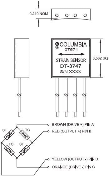
Image Credit: Columbia Research Laboratories, Inc.
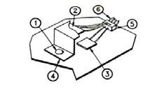
Typical Installation of Old Style Strain Gages. 1. Bolt or rivet removed from assembly; 2. Dummy gage(s) bonded to “Z Tab” of same material as structure; 3. Active gage bonded to structure under test; 4. “Z Tab” mounted to structure with bond or rivet; 5. Strain gage leads interwired and soldered to junction block; and 6. Entire unit covered with protective material. Image Credit: Columbia Research Laboratories, Inc.
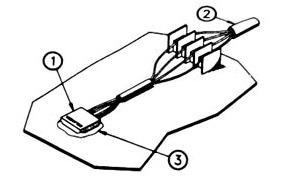
Installation of Columbia Strain Sensor. 1. Strain Sensor bonded to surface under test; 2. Leads connected to wire harness; and 3. Coat sensor and wires with waterproofing material. Image Credit: Columbia Research Laboratories, Inc.
Ordering Information*
Table 4. Source: Columbia Research Laboratories, Inc.
| Model |
Lead Length |
Compensating Material |
| DT3747-1 |
24" |
Aluminum 7075-T6 or 7050-T73651, IVD |
| DT3747-2 |
24" |
Steel, AISI 4130 or HP9-4-.20 |
| DT3747-3 |
24" |
Titanium TI-6AL-4V Annealed |
| DT3747-4 |
24" |
Carbon/Epoxy MMS 549 Type 1 |
*Mounting Radius Required upon Ordering
Advantages
- Twice as much output
- A higher level of precision
- No compromise on structural integrity
- Installation time is reduced
- Optimal temperature compensation