In industrial settings, ammonia is renowned for its toxic, hazardous and combustible nature. Undetected ammonia leaks in storage facilities and production plants can have catastrophic consequences, including accidental yet devastating explosions, fires and loss of life at the plant level, with the real possibility of damage impacting nearby communities.
Exposure
A number of gases in industrial settings can have adverse effects on worker health. Acute exposure to ammonia can lead to corrosive injury to the mucous membranes of the eyes, lungs, gastrointestinal tract and the skin because of its alkaline pH and its hygroscopic nature.
Prolonged irritation of the respiratory tract can come from chronic exposures and may result in chronic cough, asthma and lung fibrosis (Agency for Toxic Substances and Disease Registry, Centers for Disease Control and Prevention). Around the world, over 700 chemical substances have been tagged with industry-wide exposure limits.
For ammonia, the Occupational Safety and Health Administration (OSHA) recommends an 8-hour exposure limit of 25 ppm and a short-term (15-minute) exposure limit of 35 ppm in the workplace.
Regulations and recommendations vary around the world, and they are periodically updated as more information becomes available, so limit values should be cross-referenced with respective national agencies and/or organizations prior to proper usage.

Image Credit: MSA - The Safety Company
Ammonia Gas Detection
When assessing which gas sensors are best for use in occupational exposure evaluation, there can be numerous competing types from which to choose.
For most industrial hygienists, the best strategy for ensuring plant safety is to follow a multi-sensor layered approach with strategic detection positioning that offers a very secure web of coverage to safeguard against accidental gas releases.
Choosing the appropriate sensor(s) for a particular application can be complicated and requires a good knowledge of the conditions in which they will be installed (e.g., settings prone to humidity, temperature swings or interferant gases) as well as the particular benefits and limitations of each sensor type.
A number of performance characteristics should be assessed and prioritized before purchasing a gas sensor; these include sensitivity, response time, selectivity, calibration requirements and limits of detection, to name a few.
The most frequently used ammonia gas sensing technologies are described below in relation to their operating principles, and advantages and disadvantages.
Laser-based Gas Detection Technologies
Laser-based technologies, such as photoacoustic infrared (PAIR) and open-path laser (OPL), are based on the quantitative nature and specificity of absorption spectroscopy. More precisely, the physical basis on which this system works is infrared absorption of molecular gases, which applies the ammonia absorption spectral signatures of infrared radiation.
A laser-based solution should primarily aim for the sensitive, selective and rapid detection of ammonia; otherwise, the relatively expensive laser is likely not a very good choice. They have a broad dynamic range and are not degraded or consumed by exposure to high concentrations of ammonia.
Absorption spectroscopy is predicated on a novel signature attenuation of spectral intensity caused by the target gas. It occurs when light radiation interacts with molecular species, and it is stipulated by the Beer-Lambert Law:
It (λ) = I0 (λ) e-α (λ) L
Where It (λ) and I0 (λ) are the transmitted and incident light intensities at wavelength, λ, of the laser, respectively, and L is the path length. The absorption coefficient α (λ) can be written as:
α (λ) = C x ε (λ)
Where C is the concentration of gas, and ε (λ) is the specific absorptivity of the gas.
Essentially, the Law expresses that for a constant path length, the intensity of the incident light energy traversing an absorbing medium exponentially decreases with concentration, as exhibited in Figure 1 (CLU-IN, EPA).

Figure 1. Illustration of Beer’s Absorption Law. Image Credit: MSA - The Safety Company
In a laser-based IR instrument (shown below), a gas sample is inserted into the measurement chamber of the monitor, and the sample is subjected to a particular wavelength of IR light. If the gas of interest is present, it will absorb a certain amount of infrared light relative to the concentration of gas present in the sample.
In this article, an optical and a non-optical laser-based detection scheme are evaluated with respect to a potentially suited ammonia detection application.
The two different detection schemes are predicated on tuneable diode laser absorption spectroscopy (TDLAS) with a photodetector (optical) and photoacoustic spectroscopy (PAS) with a microphone as a detector (non-optical).
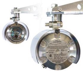
Image Credit: MSA - The Safety Company
Photoacoustic Infrared (PAIR)
In photoacoustic detection, the selectivity of conventional infrared gas spectrometry is improved further by the high sensitivity of photoacoustic spectroscopy, which employs a gas-microphone method to identify the presence of ammonia. The fundamental structure of this system is presented in Figure 2 (Applied Engineering in Agriculture, ASABE).
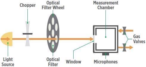
Figure 2. Schematic of a photoacoustic gas detector’s operation. Image Credit: MSA - The Safety Company
The IR light from a tungsten lamp is initially modulated using a mechanical chopper and then fed through a narrow-band optical filter to eliminate all wavelengths with the exception of the target gas’s “measuring wavelength” characteristic.
The target gas molecules become energized in the measurement chamber upon light absorption and dissipate the energy absorbed in the form of heat. The chopper-modulated pulsed light results in intermittent heat expansion and contraction of the sample air, generating a standing pressure or sound wave.
The resulting acoustic signal is recorded by a highly sensitive microphone and translated into an electrical signal associated with gas concentration, which can be determined by the following equation:
S = M · Pν · (Cω · η · c · αν + Ab)
Where S signifies the microphone signal at the light modulation frequency ω, M represents the microphone sensitivity, Pν characterizes the optical power for the excitation, the photoacoustic cell constant is represented by Cω, and the absorbed light conversion efficiency of the energy into heat is signified by η.
According to Beer and Lambert, the frequency-dependent gas-specific absorption coefficient can be defined as αν, and c signifies the gas concentration. Moreover, Ab characterizes the “zero-gas” background signal that ideally should be zero or as close to zero as possible.
Due to the fact that the optical filter will only pass the specific wavelength of light for the gas in question, a pressure pulse suggests the presence of the gas. If there is no occurrence of a pressure pulse, then no gas is present. Therefore, temperature or pressure changes will not impact the zero reading on the unit.
Additionally, this zero reading will not be influenced by the aging of the IR source or microphone since the zero is predicated on an absolute, true zero reading and not the difference between two readings as in conventional IR.
For installations that need to be able to detect ammonia at low levels, specifically in an environment where cross-sensitivity is a problem, photoacoustic infrared monitors are a prime choice, as they offer precise, high-performance monitoring for a wide range of gases.
Tunable Diode Laser Absorption Spectroscopy (TDLAS)
Another technology that employs the effect of light absorption by ammonia is laser-based open path gas detection. This sensor technology uses Enhanced Laser Diode Spectroscopy (ELDS) by measuring concentrations (ppm.m) over the entire distance between the transmitter unit and receiver unit.
The Fourier transform technique is used to analyze the absorption signal. This transforms the signal into a frequency domain from a time domain. The consequent component frequencies are then compared against a preset pattern (Harmonic Fingerprint) to confirm if ammonia is present.
This technology helps wipe out false alarms from interference gases and is less vulnerable to interference from water vapors, offering increased reliability and performance in difficult environments such as rain or fog. It is well-suited for outer perimeter monitoring along property fence lines to protect against a specific toxic gas passing beyond the boundary of a facility.
Traditional Gas Sensing Technologies
Consideration should be given to alternative sensing technologies, such as electrochemical (EC) sensors and catalytic bead sensors for combustible gas detection, depending on the application, to either supplement laser-based sensors or used to achieve suitable levels of facility safety.
Unlike their laser-based counterparts, these sensors are usually smaller in size and have lower overall unit costs, but they also present a number of limitations. Electrochemical (EC) Sensors work on similar principles to those found in batteries.
The basic structure is usually comprised of a gas-permeable hydrophobic membrane (barrier), an electrolyte, a counter electrode (or auxiliary electrode), a sensing electrode (or working electrode) and, occasionally, a third reference electrode, as displayed in Figure 3 (Chemical Exposure Evaluation).
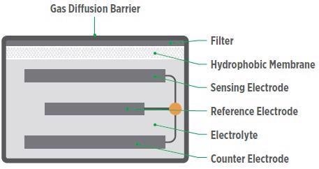
Figure 3. The basic structure of an electrochemical sensor. Image Credit: MSA - The Safety Company
When the target gas passes into the sensor via the membrane, a chemical reaction takes place at the sensing electrode with the help of a catalyst and electrolyte solution. This reaction produces a release of electrons, whereby the flow of the electrons is measured as current within the sensor.
Consequently, the current is relative to the gas concentration, and the measurement of the reaction is conducted in parts-per-million (ppm) of the gas.
This process is characterized by the following electrochemical reactions: Ammonia (NH₃) oxidizes at the anode (sensing electrode) to create nitrogen (N₂) and hydrogen “protons” (H+ ). For every two molecules of ammonia that are oxidized, six electrons (e– ) of electricity are generated:
2 NH₃ N₂ + 6 H+ + 6 e–
The counter electrode operates as a cathode with the aim of completing the circuit to enable the charge to flow. This second step (reduction reaction) takes place where hydrogen protons generated in the first half of the reaction react with oxygen to create water:
O₂ + 4 H+ + 4 e– 2 H₂O
EC sensors can enable sensitive and selective analyses of numerous gas-phase species at a rapid time resolution (typically on the order of seconds) and are comparatively lower in cost compared to other sensors. Their compact size also facilitates detection in a diverse range of locations.
However, they do have a number of limitations to consider as they are impacted by environmental conditions and have relatively short life expectancies compared to other plant safety equipment.
Most conventional electrochemical sensors have a 1-2 year life, but realistic lifetimes can be just a few months or weeks when ammonia concentrations are high or extreme fluctuations in temperature or humidity are experienced.
Predicting when a sensor will lose sensitivity can be a difficult task, so regular calibration of EC sensors may be necessary to ensure accurate readings.
They degrade at a faster rate when subjected to significantly polluted conditions. For instance, the lifespan of ammonia EC sensors is closely linked to its exposure to ammonia because as the reaction occurs, the electrolyte is consumed.
Exposures to high temperatures can expedite the evaporation of the electrolyte, thus limiting sensitivity and lifespan further.
Another drawback of EC sensors is cross-sensitivity to non-targeted gases or interfering gases that the sensor can also detect, which can produce erroneous measurements of the desired gas.
It is crucial to understand the possible effects of interferants on each type of EC sensor in operation. Depending on the reaction, the interfering effect can generate a false lower or higher concentration than the actual measurement (Chemical Exposure Evaluation).
XCell® Electrochemical Sensing Technology
MSA’s patented XCell technology applies the same fundamental principles found in conventional electrochemical sensors but with several physical design advancements.
Instead of a common water-based electrolyte, XCell Sensors use a novel class of ionic electrolyte liquids that features an evaporation-resistant profile with the capacity to withstand extreme environments with significant humidity and temperature fluctuations (-40 °C to +60 °C).
Another key difference is the choice of catalyst in the electrode material. In contrast to conventional electrochemical sensors, the XCell catalyst remains intact after the gas reaction. Thus, ammonia contact has practically no effect on the lifespan of the sensor.
They can endure background gas concentrations without limiting the lifespan of the sensor. The sensor’s mechanical design is also optimized for operational efficiency.
The sensor’s components have been strategically arranged, and the placement of components has been optimized to develop the most effective interaction between the electrolyte, electrode catalyst and target gas, irrespective of environmental conditions.
With these improved features, XCell ammonia sensors have a lifespan that is expected to exceed five years operation time, and they are supported with a three-year warranty.
These advancements in the design are crucial in enhancing sensor performance and lifetime, which can help keep plants safe from ammonia gas leaks while reducing the maintenance cost for the user.
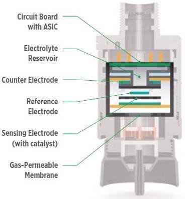
Figure 4. The basic structure of an XCell electrochemical sensor. Image Credit: MSA - The Safety Company
Catalytic Bead Technology
The operating principle of catalytic bead gas sensors is contingent on catalytic combustion to detect combustible gases in air at LEL (lower explosive limit) concentrations. The selected gas is burned by way of a heated catalyst (a coated wire coil). The electrical resistance of the wire increases in parallel with the temperature increases.
A regular Wheatstone bridge circuit employs two wire coil elements (one for detection and one for compensation) to convert the raw temperature change to signal the presence of combustible gas.
Typically speaking, these sensors have a long life and are less vulnerable to changes in temperature, humidity, condensation and pressure.
However, they are also prone to sensor poisoning and shortened life with continuous or frequent exposure to high measured gas concentrations.
Another drawback is that they monitor a broad range of combustible gases and vapors in air and are therefore not specific to ammonia gas detection.
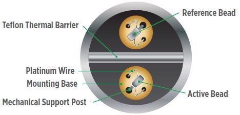
Figure 5. Catalytic bead sensor. Image Credit: MSA - The Safety Company
Ultrasonic Gas Leak Detection (UGLD)
UGLD technology is able to detect leaks from pressurized gas systems by sensing the airborne ultrasound the escaping gas produces. This means that detection speeds of the ultrasonic gas leak detectors are close to the speed of sound in a sensing radius up to 28 meters (92 ft) depending on the gas, leak rate and size.
Contrary to other gas detection methods, like point or open path previously mentioned, ultrasonic gas leak detectors do not have to wait for a potentially dangerous gas cloud to accumulate and come into direct physical contact with the detectors. They raise an alarm instantaneously as soon as a leak is detected.
The ultrasonic acoustic gas leak detector identifies the leak without being influenced by conditions such as gas dilution, changing wind directions and the direction of the gas leak — conditions relevant for most outdoor gas installations.
However, one of the drawbacks of UGLD is that they are ill-suited for low pressure leaks and are not able to determine the concentration of ammonia being released. They are an excellent choice as a first line of defense due to their minimal maintenance requirements, rapid response time and environmental versatility.
Conclusion
Ammonia gas sensor technology has improved significantly in recent decades. Compared with the systems 20-30 years ago, new designs and the introduction of ionic liquids in the chemistry of electrochemical (EC) sensors have had a positive impact.
Moreover, they can be assisted by other ammonia detection technologies, including open path gas detectors, Enhanced Laser Diode Spectroscopy (ELDS) Photoacoustic IR monitors and Ultrasonic gas leak detectors.
As improvements continue, combining new technologies into a single application is becoming an increasingly common practice. When evaluating a plant’s safety requirements, users should take into account a layered strategy to develop the most comprehensive gas detection system for the facility.
There is no outright perfect singular solution, so fully understanding the monitoring environment and the particular benefits and limitations of the chosen sensors is absolutely vital to ensuring optimal plant safety.

This information has been sourced, reviewed and adapted from materials provided by MSA - The Safety Company.
For more information on this source, please visit MSA - The Safety Company.