Ultrasonic system designers have multiple options when using an ultrasonic transducer, including frequency, housing design, and mounting options. A crucial aspect of the system design process involves weighing the trade-offs between transducer performance, acoustic beam characteristics, and integrated electronics.
Various factors, such as the properties of the propagating media, environmental conditions, and electronics, may impact the performance of the transducer. When choosing a transducer for a specific application, multiple parameters must be taken into account. This article aims to identify the essential factors that must be considered.
Maximum Sensing Range
When designing an ultrasonic system, it is essential to consider multiple factors that can influence the maximum sensing range of a transducer.
In addition to the transducer itself, atmospheric conditions, drive and receive electronics, and signal processing are among the crucial factors that must be taken into account. In this regard, it is necessary to discuss some of these factors.
Temperature and Humidity
Temperature variations can impact the sound speed of air, as well as the materials of the ultrasonic transducer.
Operating the transducer at temperatures significantly higher or lower than its optimized range can lead to the "detuning" of the acoustic matching layer and the shifting of the resonant frequency, which can cause a decline in performance.
The resonant frequency may shift approximately -0.8% per 10 °C (-0.8% per -10 °C), resulting in a reduction in sensitivity that is generally acceptable for most applications. However, corrections may be necessary for applications that experience a broad temperature range.
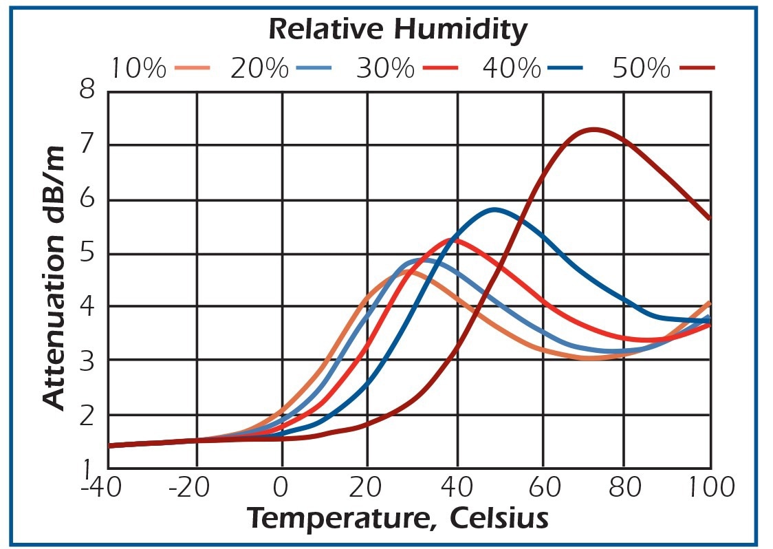
Figure 1. Signal attenuation in air at 1 atmosphere at 100 kHz. Image Credit: AIRMAR Technology Corporation
Environmental conditions can significantly alter the properties of air. Figure 1 demonstrates that signal attenuation is dependent on factors such as temperature, humidity, frequency, and air pressure. Meanwhile, the speed of sound primarily depends on temperature, as illustrated in Figure 2.
Although humidity has a minor effect on sound speed, resulting in less than a 0.6% change in speed within the shown temperature range, some transducers feature optional internal thermistors to compensate for the speed of sound. External temperature sensors can also be used for precise calibration across a broader range.

Figure 2. Speed of sound in air. Image Credit: AIRMAR Technology Corporation
Air Currents and Atmospheric Influences
Air turbulence can impede the maximum measurement range as it has the potential to deflect or weaken sound waves, ultimately resulting in reduced echo signals. Air currents carry sound downwind, and significant currents can deflect sound so much that it may miss the desired target. Large, abrupt temperature changes can also reflect sound.
Light snow or rain in the path of sound waves can attenuate them, reducing range. Lower frequency transducers release longer wavelengths, meaning that the deteriorating impact of snow and rain is less significant than for higher frequencies.
Interference
(Electrical and Acoustical)
Air-ranging ultrasonic transducers, which may be vulnerable to RFI and EMI, can be equipped with internal shielding as a standard precaution. However, certain environments may necessitate the use of additional shielding.
High-pressure air nozzles, such as blow-off guns, generate significant levels of ultrasonic noise, which is broad in frequency and challenging to filter out. Consequently, it is advisable to avoid installing transducers near air nozzles.
If a transducer is to be mounted on vibrating equipment, it may be subjected to mechanically coupled interference. To minimize the transmission of vibration to the transducer, a highly compliant mounting material should be used.
Target Strength
Targets that are hard, smooth, flat, and mounted orthogonally to the transmitted beam will provide the strongest signals and thus be detectable at longer ranges. Examples of such targets include liquid, glass, or metal.
If the beam is not orthogonal, it will be reflected off at the angle of incidence and not be received by the transducer. For instance, a transducer with a 10° beam angle will experience a 3 dB signal degradation if the target is misaligned by 2.5°.
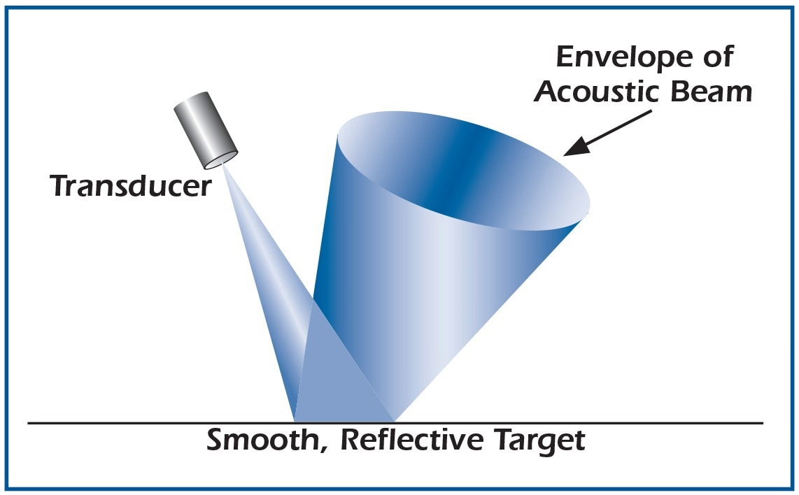
Figure 3. Sound reflective at the angle of incidence. Image Credit: AIRMAR Technology Corporation
When a surface is rough and irregular, the returned signal's amplitude is variable due to the scattering of sound. Such targets have the disadvantage of smaller return signals but the advantage that the target's alignment is less critical.
Different materials have widely varying abilities to reflect sound. Surfaces such as fabric and foam have the lowest reflectivity, resulting in low amplitude echoes and thus significantly reducing the effective range of the transducer.
Beam Angle
A transducer emits energy in a specific beam pattern, with the majority of the energy concentrated in the main lobe that defines the beam width. However, energy outside the main lobe is concentrated in sidelobes.
These sidelobes can generate phantom echoes, which can obscure the actual location of targets. While no transducer can be completely free of sidelobes, most air-ranging ultrasonic transducers are designed to have low sidelobe levels, at least 17 dB below the main lobe.
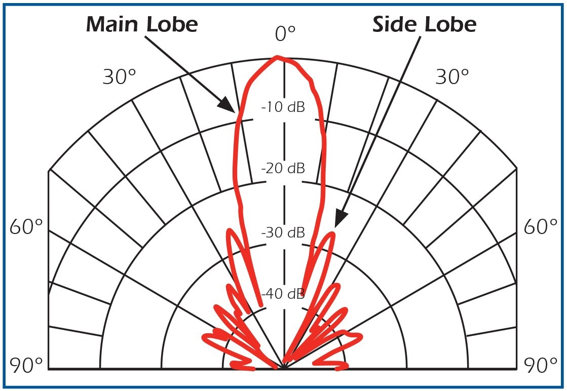
Figure 4. Typical beam pattern. Image Credit: AIRMAR Technology Corporation
Transducers with wide beam angles have a reduced sensing range and lower target discrimination than narrow beam models. This is because wide beams spread acoustic energy over a larger volume, resulting in less energy being reflected from potential targets compared to a narrower, more concentrated beam.
Conversely, narrow beam angles tend to have greater variations in echo amplitude with irregular surfaces, such as a wavy fluid target, compared to wide beams.
Minimum Sensing Range
The minimum sensing range of a transducer, measured from its active surface, is referred to as the Blanking Zone. No echo signals can be received within this zone, and ideally, this distance should be zero.
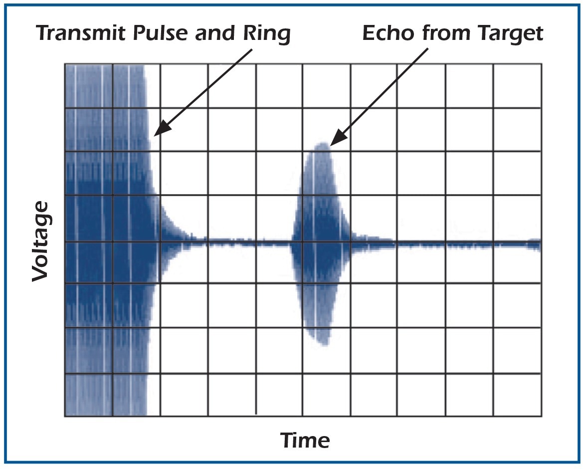
Figure 5. Transmit ring example. Image Credit: AIRMAR Technology Corporation
The blanking zone is caused by a phenomenon called ringing, which is the continued vibration of the piezoelectric transducer element beyond the electrical excitation pulse.
Due to the nature of piezoelectric ceramics and the limitations of transducer design, some amount of ring time is inevitable to dissipate mechanical and electrical energy after excitation ceases.
The extent to which a transducer rings depends on its design. The amount of ring will also vary slightly from transducer to transducer of the same design due to manufacturing tolerances.
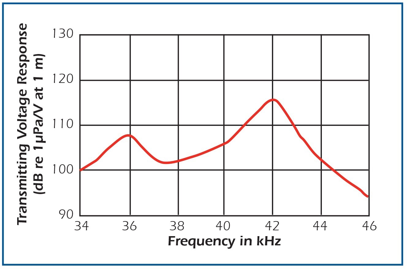
Figure 6. Transmitting response showing adjacent responses. Image Credit: AIRMAR Technology Corporation
The amount of ring a transducer exhibits can be influenced by the type of electrical pulse used to drive it. When a tone burst drive is used, which consists of ten cycles at the best operating frequency, the amount of ring time can be characterized. A transducer has multiple vibration modes, some of which are strongly coupled to air while others are not.
It is important to drive the transducer at a frequency strongly coupled to air and avoid exciting extraneous resonances during system design. Hence, the use of a tone burst (narrow bandwidth) is beneficial.
On the other hand, a wide-band transmit scheme can stimulate undesirable vibration modes, such as those generated by "impulse" drive electronics, which apply a high-voltage, short-duration burst of energy to the transducer. When undesirable frequencies are stimulated, ring time increases as they dissipate their energy more slowly.
All air transducers have a secondary resonance next to the desired resonance frequency. This secondary resonance is caused by the use of an acoustic matching layer to enhance the coupling between the piezoelectric ceramic element and air.
Figure 6 illustrates that the secondary resonance is more weakly coupled to air and exhibits greater ringing than the desired resonance.
Mounting
As an electromechanical device, the transducer transmits vibrational energy to its housing. The vibrations can be accentuated when rigidly mounted, resulting in prolonged ring time. The transducer's performance is minimally affected by a compliant mount. It is not advisable to forcefully mount the transducer into a press-fit location.
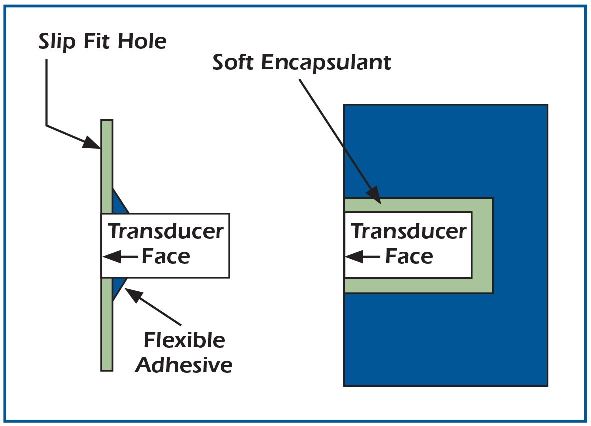
Figure 7. Mounting examples. Image Credit: AIRMAR Technology Corporation
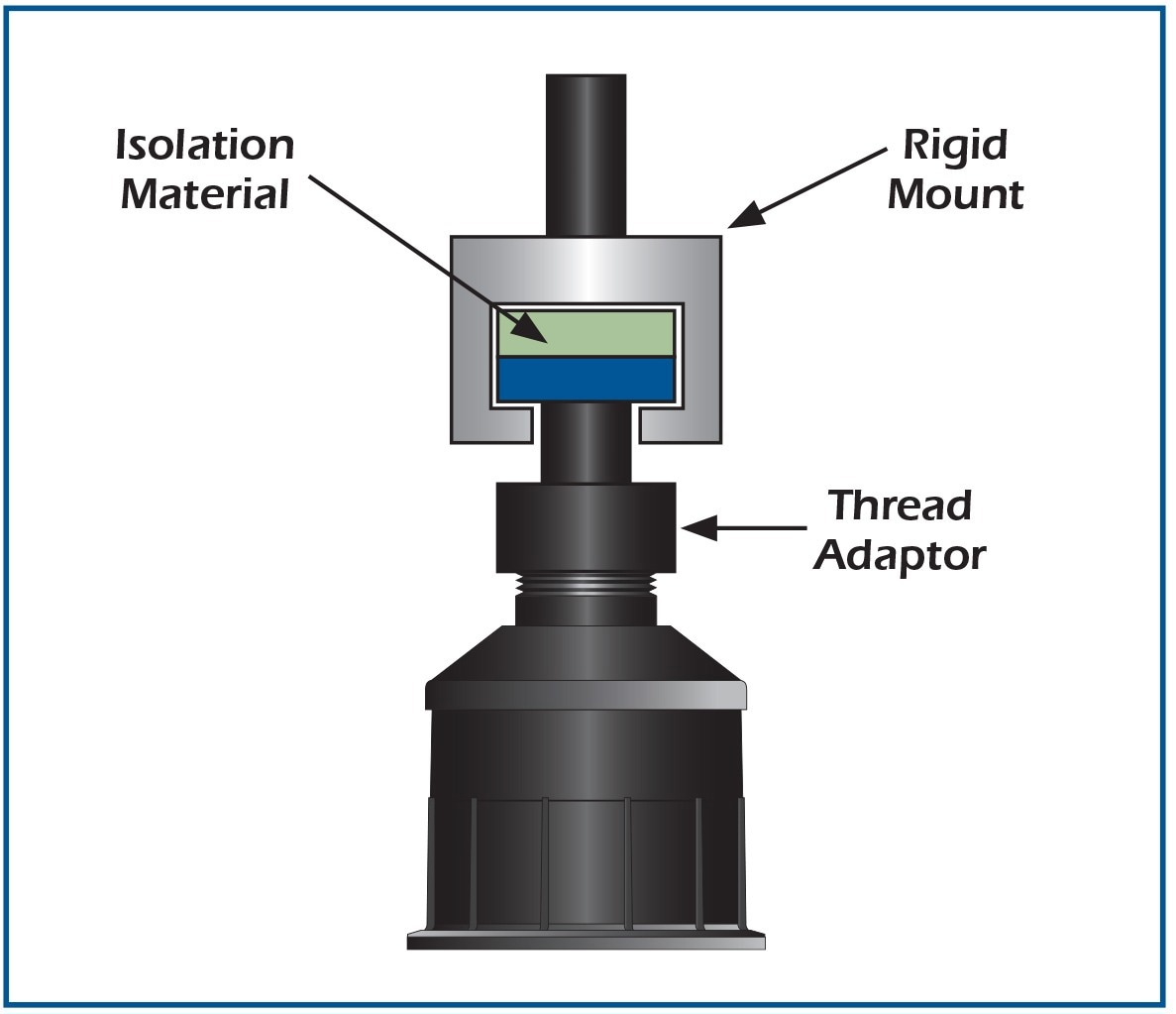
Figure 8. Isolation bushing example. Image Credit: AIRMAR Technology Corporation
Mounting the transducer on the housing's outer diameter may lead to increased ring time. Therefore, it is recommended to use an isolation bushing, as shown, to provide additional isolation when necessary.
Air-Ranging Transducers from Airmar Technology
Airmar manufactures top-quality non-contact ultrasonic air transducers that are widely trusted in today's challenging commercial and industrial applications.
The AIRDUCER® air-ranging transducers play a critical role in the development of numerous measurement systems used in various fields, including liquid or solid levels, flow control, automation control, proximity sensing, obstacle avoidance, distance measurement, and inventory control.
These transducers are manufactured in the United States and are preferred by engineers and system integrators who demand superior quality and unmatched performance from every component.
Airducer transducers are safe, rugged, reliable, and factory-tuned, ensuring optimal functionality in harsh environments. Additionally, they have sealed housing and are rated IP68, with no moving parts that could wear out.

This information has been sourced, reviewed and adapted from materials provided by AIRMAR Technology Corporation.
For more information on this source, please visit AIRMAR Technology Corporation.