Fluid power is a crucial aspect of hydraulic applications that utilizes pressurized fluids to generate, control, and transmit power. These systems produce high forces and power in relatively small volumes and long lifespans.
Self-propelled scissor lifts, injection molding, machine tools, steelmaking and metal extraction, paper industries, textile machinery, disability lifts, security, and parking barriers are just a few industrial applications that rely on fluid power.
Pressure sensors play a vital role in ensuring the efficiency and safety of these systems. By providing feedback to a Program Logic Controller (PLC), pressure sensors aid in controlling fluid pumps and maintaining system pressure within a specified range.
If a pressure sensor fails in these applications, it can interrupt the feedback loop of motor control, potentially leading to equipment failure, costly downtime, or even safety hazards for workers.
Challenges and Top Five Specifications to Consider for Pressure Sensor Selection
To specify the most suitable pressure sensor for a given system, it is imperative to comprehend the operating conditions and environment of the application. In the case of hydraulic applications, identifying and addressing prevalent challenges can aid in determining the appropriate specifications for the job.
High Pressure
To ensure the safe and reliable operation of applications characterized by high fluid pressures exceeding 50 bar (725 psi), it is essential to have robust components explicitly designed to withstand such pressures.
These systems may involve hazardous fluids and the combination of high pressures and temperatures, making any potential leaks very dangerous.
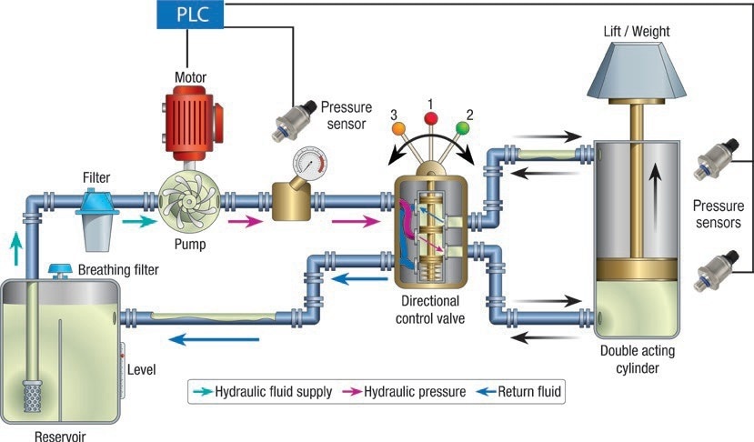
Figure 1. Pressure sensors play critical roles in hydraulic applications, typically involving high pressure of more than 50 bar (725 psi). Image Credit: Sensata Technologies, Inc.
Sense Element Technologies
There are several commonly used sensor technologies for high-pressure range applications beyond 50 bar (725 psi), each with its advantages and disadvantages.
Thick Film Ceramic sense elements are manufactured by printing four resistors, arranged in a Wheatstone bridge formation, onto the non-process side of a ceramic substrate.
As pressure is exerted onto the process side of the substrate, the ceramic deforms, leading to a physical alteration in the resistors and, subsequently, a shift in the electrical output signal.
When utilized in high-pressure systems, such as hydraulic applications, the ceramic substrate is more vulnerable to cracking and breaking from repetitive high-pressure cycling and high-pressure spikes when compared to alternative metal substrate technologies.
Due to the inability to weld ceramic sense elements to the process connection, an accompanying o-ring and locking mechanism are necessary to establish the seal. This added step increases the complexity of the sensor design and could potentially result in leaks and failures.
Thin Film Metal sensing elements utilize the process of thin film deposition to create a Wheatstone bridge pattern of resistors onto a substrate. The sensor's electronics operation is comparable to that of thick film ceramic.
A significant advantage of thin film technology is its compatibility with various materials, making sputtering easy to implement. Moreover, because the sense element is composed of metal, typically stainless steel, it can be welded into the process port design, creating a hermetic seal that obviates the need for o-rings.
In this type of sensor element design, substandard bonding between the thin film sense element and port material may cause early component failure during endurance pressure cycling.
Thin film manufacturing involves costly sputtering process equipment and requires a clean room, resulting in higher production costs.
Through glass bonding, Micro Silicon Strain Gauge sense elements are created by bonding a silicon strain gauge to a metal substrate, such as 17-4PH or 316L stainless steel.
The substrate is welded to the pressure port to produce a hermetic process connection without an o-ring, preventing potential process fluid leaks into the sensor.
This technology offers more design flexibility than other sense element technologies due to the smaller size of the strain gauges.
The excellent glass bonding between the gauge and the stainless-steel port enhances the durability of the sensor against pressure cycling.
Although thin film sense elements provide a more linear raw output, Micro Silicon Strain Gauge technology can produce comparable accuracy through calibration, resulting in a more cost-effective sensor with the same or better accuracy.
This technology offers a relatively higher sensitivity (mV/V) than a thin film, enabling the membrane of the pressure-sensing element to be thicker, increasing the burst strength.
High-Pressure Spikes and Burst Strength
Exposure to high-pressure spikes can result in the failure and damage of components if the pressure event surpasses the component's rated burst or proof pressure.
The maximum pressure a device can tolerate without rupture for two minutes, known as burst pressure, is typically specified as a multiple of the upper limit of the device's operating pressure range.
Although repeated high-pressure spikes below a component's rated proof and burst pressures may not lead to immediate rupture, they can cause damage to pressure diaphragms over time, resulting in potential sensor failure and system leaks.
A sensor's burst pressure tolerance is influenced by the internal port geometry and diaphragm thickness of the sense element. Snubbers can be employed to shield pressure sensors from repeated high-pressure spikes.
These devices decrease the aperture size through which the fluid flows, damping the pressure spike before the fluid reaches the sense element. For instance, in construction machinery, sudden stops or starts, or sharp vehicle turns frequently expose the system and components to significant pressure spikes.
In such scenarios, a 10x burst strength rating ensures that the components retain their structural and operational integrity.
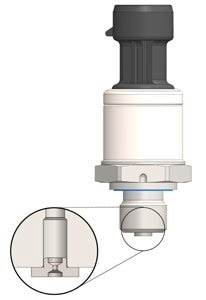
Figure 2. Pressure sensors like Sensata’s PTE7100 have greater than or equal to 10x burst strength up to full scale pressure range of 600 bar and can be configured with a snubber to dampen pressure pulses and help prevent component failure in hydraulic applications where high-pressure spikes are a concern. Image Credit: Sensata Technologies, Inc.
Shock and Vibration
Hydraulic systems involve various moving components, such as pumps, motors, and large cylinders, which generate vibration. These systems are often integrated into larger systems that may experience or cause higher levels of shock and vibration.
Overexposure to these levels beyond a component's capacity to endure could damage its mechanical construction and electronics. Heavy-duty applications, including off-road equipment, scissor lifts, and forklifts, are particularly vulnerable to shocks and higher vibration levels.
Mechanical shock is a short, momentary impact that can transfer energy to a component from events such as transportation or rough handling. In contrast, vibration is a continuous mechanical oscillation that may arise from running machinery, such as engines, or an initial shock.
Pressure sensors are frequently exposed to mechanical shock and vibration in hydraulic applications and mobile machinery, compressors, and engines that form part of these systems.
It is crucial to evaluate suppliers' test standards to rate their sensors while selecting a pressure sensor for such applications. This evaluation ensures the component can withstand the system's potential shock and vibration.
Sensor suppliers usually test their sensors to IEC 60068-2-27 standards to indicate the level of mechanical shock that their sensors can withstand. A rating of 500 g min is best-in-class and would likely prevent potential damage and component failure in hydraulic applications.
Compressors and motors' frequent running in these systems implies that all components are subject to long periods of vibration exposure.
Suppliers offering more stringent testing and vibration ratings usually test their sensors to IEC 60068-2-6. By qualifying a sensor to 30 g (10…2000 Hz), more reliable and long-lasting sensing solutions in applications are provided.
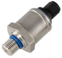
Figure 3. Pressure sensors like Sensata’s PTE7100 is rated to 30 g (10…2000Hz) vibration and 500 g min mechanical shock, making it a robust and reliable solution for hydraulic applications where components are frequently exposed to harsh conditions. Image Credit: Sensata Technologies, Inc.
Electromagnetic Compatibility (EMC)
Hydraulic applications frequently utilize high-power levels and complex machinery that render equipment susceptible to electromagnetic emissions and electrostatic discharges, potentially causing damage to the system if the components are not suitably rated.
For instance, a hydraulic pump may emit electrical noise or interference into the atmosphere without a proper ground connection. At the same time, an electric welding machine may be used on the scissor lift of a mobile aerial work platform without a solid ground connection.
These situations increase the likelihood of electromagnetic emissions impeding the sensor's signal.
To mitigate this risk, it is advisable to specify sensors that meet rigorous EMC standards, including Enhanced Radiated Immunity (EMI) ratings of at least 150 V+/m and enhanced Electrostatic Discharge (ESD) ratings of ±8 kV contact or ±15 kV air, ensuring adequate protection.
Pressure Sensors’ Critical Functions in Industrial Applications
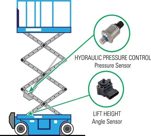
Figure 4. Pressure sensors play critical roles in scissor lifts, where they control the hydraulic pressure of the main cylinder or, when combined with an angle sensor, they can help control platform overload conditions. Image Credit: Sensata Technologies, Inc.
Safety in Scissor Lifts
In applications, such as scissor lifts, pressure sensors help control the main cylinder's hydraulic pressure, stabilizing the lift for a smooth, steady ride. In addition, when combined with an angle sensor, a pressure sensor can help control the platform overload condition, complying with ANS192 and EN280 safety standards.
In these applications, it is essential to consider the redundancy of pressure sensors, as sensor failure could lead to injury of human operators.
Reliability in Injection Molding
Though, in general terms, injection molding involves the same type of hydraulic system as in scissor lifts, some parameters differ between the applications, such as the fluids used and the motor and cylinder sizes.
In injection molding, the hydraulic system controls the actuation of the molds as they clamp together and pull apart. The pressure sensor often senses feedback on the mold actuation's hydraulics, providing feedback to the pumps so that the motion is as repeatable and efficient as possible.
A sensor failure would lead to mold downtime and reduced product output. A robust and adequately rated pressure sensor can help minimize poor injection molded part quality and prolong tool life.
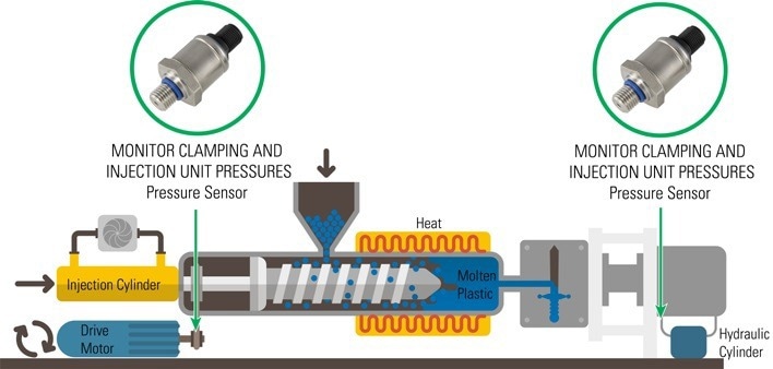
Figure 5. Using a high-quality pressure sensor in injection molding applications can help prevent downtime, minimize poor molded part quality, and prolong tool life. Image Credit: Sensata Technologies, Inc.
Pressure sensors play a critical role in hydraulic applications, where high system pressures of over 50 bar (725 psi) are common.
These components are vital in ensuring safe and efficient operation of equipment. However, a failure caused by incorrect specifications during the design process can result in dangerous working conditions and costly downtime.
Design engineers must be meticulous in considering the challenges that arise in hydraulic applications and must carefully evaluate key specifications, such as sensing technology, burst strength, shock and vibration, and electromagnetic compatibility when selecting pressure sensors for these systems.
By choosing components with more rigorous ratings, engineers can help prevent component failure and increase equipment safety and reliability.

This information has been sourced, reviewed and adapted from materials provided by Sensata Technologies, Inc.
For more information on this source, please visit Sensata Technologies, Inc.