Conventional DO sensors rely on electrochemical processes to produce signals indicating the dissolved oxygen level in liquid solutions. Nevertheless, this approach may only be suitable for some applications. Specifically, classic polarographic sensors encounter several issues listed below.
- High maintenance: These sensors necessitate regular electrolyte and membrane cap replacement.
- Long startup time: Polarographic sensors must undergo a polarization process to eliminate any residual oxygen in the sensor before use, lasting between 2 to 8 hours.
- Accuracy issues: Polarographic sensors can be influenced by gases like carbon dioxide, which can impact the pH of the electrolyte, and by mobile ions such as sulfides, which can contaminate the electrodes, affecting accuracy.
- Environmental requirements: Since polarographic sensors consume the oxygen they are measuring, they demand a constant flow or agitation of the water to prevent local depletion of oxygen levels, preserving accuracy.
These limitations have spurred significant research into alternative methods for measuring DO, with the most effective solution discovered so far being the optical DO sensor. Optical DO sensors typically comprise:
- Excitation light
- An oxygen-sensing material made up of a luminescent dye called a luminophore and a polymer matrix permeable to oxygen.
- A photodetector to gauge changes in the emitted light characteristics of the luminophore in the presence or absence of oxygen.
In addition to addressing the issues associated with traditional DO sensors, optical DO sensors offer several advantages:
- Less fouling from contaminants in the liquid (and therefore less signal drift)
- Faster response time
- Immunity against electrostatic noise
- Greater stability against pressure spikes
Fluorescence Quenching and Phase Shift
Optical dissolved oxygen (DO) sensors function based on the principle of luminescence. In specific materials, known as luminophores, electrons within the luminophore absorb the energy from the excitation light and reach an excited state.
While in this state, interactions with other molecules like oxygen can occur, as the luminophore stays excited for a defined duration (fluorescence lifetime). When the electrons return from this excited state to the ground state, they emit light, displaying luminescence or fluorescence.
Luminophore materials have an intriguing property related to oxygen gas (O2) in the excited state, which leads to two effects on the material's fluorescence characteristics. When an oxygen molecule collides with the luminophore during the excited state, the energy is transferred from the luminophore to the oxygen, resulting in two outcomes:
- The intensity of the emitter fluorescence is reduced
- The fluorescence lifetime of the luminophore is shortened
This phenomenon is called fluorescence quenching and is shown below.
Fluorescence Quenching Process
Image Credit: Hamilton Process Analytics
Optical DO sensors can detect fluorescence quenching by observing changes in intensity and fluorescence lifetime.
A connection exists between the amount of oxygen in the sample being measured and the reduction in fluorescence intensity and fluorescence lifetime, as described by the Stern-Volmer equation.
Consequently, by monitoring and gauging one of these light emission properties, the oxygen content in the sample can be ascertained.
The Stern-Volmer Equation
Both the change in fluorescence intensity and the phase shift are associated with the concentration of dissolved oxygen. This correlation is defined as the Stern-Volmer equation.
Where:
I = the measured fluorescence intensity
I0 = the reference (oxygen-free) fluorescence intensity
τ = the measured lifetime
τ0 = the reference (oxygen-free) lifetime
KSV = the fluorescence quenching constant, which is a property of the fluorescent material
[O2] = the concentration of oxygen
The straightforward and linear nature of the Stern-Volmer equation simplifies the process of converting either the measured intensity or measured lifetime into an electronic signal representing the dissolved oxygen concentration.
In the early stages of optical DO sensors, intensity alone was relied upon. However, these sensors encountered accuracy issues over extended periods of use due to factors like the fading of the dye compound and physical damage to the luminophore.
Nevertheless, utilizing phase shift as an indicator of DO concentration offers some advantages over intensity.
The relationship between phase shift and oxygen concentration follows a stable and predictable pattern. Phase shift is also less susceptible to physical damage to the luminophore. Consequently, more recent designs of optical DO sensors place greater reliance on phase shift rather than intensity.
Relationship Between Dissolved Oxygen and Phase Shift
Relationship Between Dissolved Oxygen and Phase Shift. Image Credit: Hamilton Process Analytics
Optical DO Sensor Components
An optical dissolved oxygen (DO) sensor, at its core, comprises the following essential parts:
- A light source
- A transmission medium (which can be a fiber optic or a window, allowing light to travel from the source to the fluorescent material)
- The luminophore (fluorescent dye held in a silicone gel matrix) makes contact with the aqueous solution
- A photodetector to detect the light emitted from the fluorescent dye
- Electronic circuitry to convert the detected fluorescence intensity and/or lifetime into an electronic signal
While the scientific understanding of fluorescence quenching dates back to 1939, it was not until the latter part of the 20th century that this technology started gaining substantial research attention. This was due to the limitations of electrochemical DO detection and advancements in light sources, photodetectors, and electronic signal processing.
A considerable portion of the research and development efforts in optical DO sensors has focused on the oxygen-sensitive dye found in the luminophore. There are three primary classes of luminescent compounds suitable for optical DO sensors:
- Polycyclic aromatic compounds
- Platinum-based compounds
- Ruthenium-based compounds
Each luminophore material has its pros and cons for optical DO sensing, and the specific material used in a given commercial sensor is frequently a closely guarded trade secret.
The light source and photodetector are also crucial elements. As each dye material fluoresces at a different incident light wavelength, the light source, typically a light-emitting diode (LED), must be finely tuned to the correct wavelength.
Similarly, the photodetector needs to be capable of detecting both the intensity and phase of the fluorescent emission from the dye material.
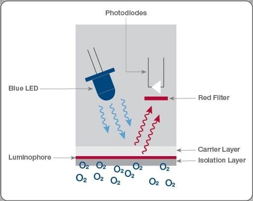
Basics of optical DO sensor measurement channel. Starting at the blue LED, photons travel to the luminophore and are emitted back to the photodiode at a frequency relative to the amount of oxygen diffused through the membrane. Image Credit: Hamilton Process Analytics
Compensation
Various environmental and operational factors, such as temperature, pressure, and component aging can influence the performance of fluorescence-quenching optical DO sensors. To ensure precise readings and prolong the device's useful life, these factors must be compensated for.
- Temperature: Changes in the water's temperature being analyzed can impact the quenching effect of dissolved oxygen, leading to reduced sensor accuracy. Most commercial optical DO sensors integrate a temperature-sensing component. The electronic circuitry utilizes the temperature signal to correct the DO reading.
- Pressure: The pressure of the surrounding air can lead to accuracy problems. The solubility of gas in water relies on the gas's partial pressure, which can be influenced by altitude and weather conditions. Most optical dissolved oxygen (DO) measurement systems allow users to input the local atmospheric pressure value. The system then uses this value to correct the DO reading.
- Salinity: The amount of dissolved salt (NaCl) in the water also impacts the solubility of oxygen gas. Similar to pressure compensation, salinity compensation can be achieved by manually inputting a separate salinity measurement.
VisiFerm® ECS
Hamilton's VisiFerm sensors, equipped with an electrochemical signal (ECS) output, convert the photodetector output into the typical nano-ampere (nA) level output found in traditional polarographic DO sensors. The ECS interface is a great choice for replacing existing bioreactors' polarographic sensors.
Many DO transmitters currently on the market require an nA signal, making it possible to retrofit the VisiFerm ECS to work with these products. It also includes the output from a 22-kΩ NTC temperature sensor, enabling temperature compensation via external electronic circuitry.
VisiFerm® RS-485
VisiFerm RS-485 DO sensors integrate a built-in micro-transmitter within the sensor. The output of these sensors is either a 4–20 milliampere (mA) analog output or a Modbus digital signal.
Hamilton's Arc technology compensates for temperature fluctuations and adjusts for input pressure and salinity values within the sensor itself, eliminating the need for external compensation circuitry.
As a result, the output signal is fully compensated. One advantage of this design is that VisiFerm RS-485 sensors can be directly connected to the process control system (PCS) without requiring a secondary transmitter.

This information has been sourced, reviewed and adapted from materials provided by Hamilton Process Analytics.
For more information on this source, please visit Hamilton Process Analytics.