Something that has caused quite the stir around the design engineering community in recent years is the development of printed, thin, and flexible sensors. This is largely due to the rapid growth of lightweight, smart, and power-efficient technologies, which have become ingrained into our everyday lives. Naturally, when designing powerful compact devices and products, the components implanted to make them should also share those same game-changing innovations.
Force sensing resistors (AKA, printed force sensors, or force sensitive resistors) are a large continually expanding group of embedded components, with the introduction of numerous new sensor types in recent years. Yet, force sensing resistors are by no means a new technology. In fact, the use of force sensing resistors as an embedded component has been in production for decades.
This article communicates the fundamentals of force sensing resistor technology, how they work, and how they can be used to capture force measurements as an embedded component within a device.
How Do Force Sensing Resistors Measure Force?
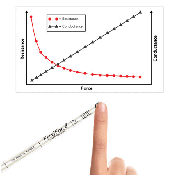
Figure 1: When force is applied to a force sensing resistor, the conductance response as a function of force is linear.
Most engineers have been taught that the formula for force is the mass of an object multiplied by its acceleration (or, F=M*A), or, multiplying the applied pressure by the contact area (F=P*Area). There are multiple engineering units that correspond to “F” in these equations, such as Newtons (N), pound-force (lbf), among others.
Force sensing resistors are not ordinarily pre-calibrated to connect a force reading to a known engineering unit. However, via a calibration procedure, the force measurement output recorded by a force sensing resistor can be correlated to the applied force.
Force sensing resistors are passive elements that operate as a variable resistor in an electrical circuit, making them a piezoresistive sensing technology. The indications in Figure 1 show, when unloaded, the high resistance of the sensor (on the order of Megaohms (MΩ)) decreases as force is applied (usually on the order of Kiloohms (KΩ)). Therefore, when taking into consideration that which is contrary to resistance (conductance), the conductance response as a function of force is linear within the defined force range of the sensor.
How Do You Calibrate a Force Sensing Resistor?
Force sensing resistors can be calibrated with just two-to-three known loads, this is because of the resistance/conductance linear relationship. Each stage of the calibration process is thoroughly detailed in this article.
The sensor’s sensitivity can also be varied for optimal performance in your specific force range if your circuit is designed with adjustable components. This article further clarifies the value of adjustable sensitivity.
How Are Force Sensing Resistors Made?
Force sensing resistors are made up of a semi-conductive material – or, semi-conductive ink – fastened between two thin substrates. There are two different types of force sensing resistor technologies available – Shunt Mode, and Thru Mode – as shown in Figure 2.
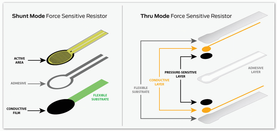
Figure 2: This graphic illustrates the differences between shunt and thru mode force sensing resistor technologies.
Comprising of two membranes separated by a thin air gap, shunt mode force sensing resistors are polymer thick-film devices. While one membrane is coated with a special textured, resistive ink, the other has two sets of interdigitated traces that are electronically isolated from one another.
Thru mode force sensing resistors are ductile-printed circuits with the ability to utilize a polyester film as its two outer substrates. Placing silver circles with traces above and below a pressure-sensitive layer, followed by a conductive polymer, an adhesive layer is used to laminate the two layers of the substrate together.
Matrix or Single-Point Force Sensing Resistors
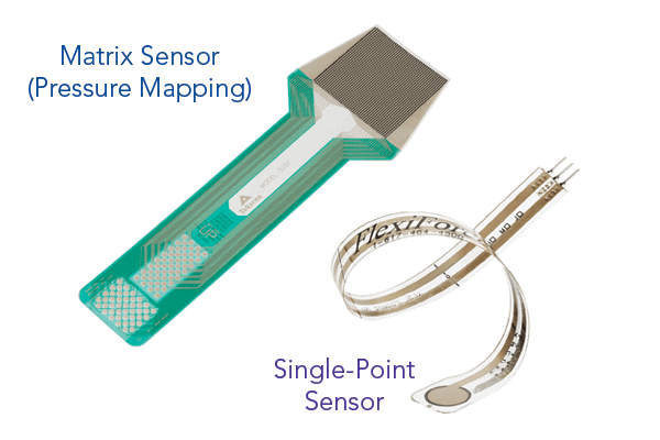
Figure 3: Examples of different force sensitive resistor technologies.
Force sensing resistors can be designed in a matrix array form, or as single-point force sensors enabling the user to capture pressure distribution over a determined area. These force sensing resistor matrices are typically known as pressure mapping technology.
Tekscan’s FlexiForce™ sensors are a variety of thru mode force sensing resistors. Due to the technology’s flexible nature and ability to function on simple circuitry, combined with their operating capabilities, make them an excellent choice for embedding into smart devices with limitations on power and size. FlexiForce™ sensors can be customized and tailored in size, shape, sensitivity, operating temperature and electrical termination, to meet your application’s specific needs.
This article covers the many differences between shunt and thru mode sensor technologies and performance, including how they compare on precision, linearity, drift, and other key concerns.
How Are Force Sensing Resistors Used?
Although new applications for force sensing resistor technology are being discovered every day, most tend to fall under four different use categories:
- Measuring or detecting a rate of change in force
- Measuring or detecting a relative change in force
- Detecting contact and/or touch
- Detecting force thresholds to trigger an action of some sort (e.g. IoT applications)
Further visual context around these different use cases for force sensing resistors – specifically FlexiForce™ force sensing resistors – can be seen in this short video:
FlexiForce: Integrate Force Sensing Ingenuity Into Your Product
Are You Interested in Purchasing Force Sensing Resistors?
Tekscan offers a selection of standard FlexiForce™ force sensing resistors in low-quantity, low-cost packs, on their online store. Furthermore, Tekscan offers OEM proof-of-concept and integration kits and force measurement systems to assist you in all of your force measuring needs.
For any other questions on force sensing resistor technology, contact a Tekscan engineer today.

This information has been sourced, reviewed and adapted from materials provided by Tekscan, Inc.
For more information on this source, please visit Tekscan, Inc.