As the demand for compact and sleek devices grows on an international scale, design engineers are constantly facing difficulties in fitting more smart capabilities into a constantly decreasing design space. As such, sensing technologies and printed electronics of various types have gained much interest among the global design engineering communities.
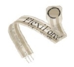
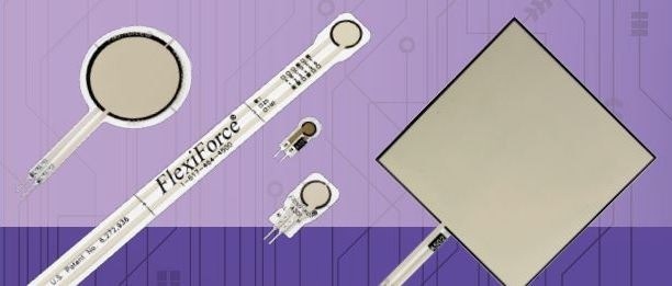
Printed force sensor technologies such as FlexiForce™ sensors are an ideal option for design engineers looking for ways to integrate force feedback capabilities into their device.
Whether the application demands the mechanical or manual human measurement of force feedback, printed force sensors are a perfect method for embedding force-sensing capabilities without impacting size or increasing the weight of a design.
Further than their apparent physical features, there is a lot more information for design engineers to know about printed force sensors. The flexible and thin form factors of printed force sensors may result in design engineers questioning their linearity, durability, and limitations within an operating environment. This eBook will surprise the reader in outlining the capabilities that this technology has to offer.
This eBook will cover the top five most frequently asked questions concerning printed force sensor technologies, and will finish with some examples of how this sensor technology has been creatively used in OEM applications.
1. How Are They Constructed?
Also known as force-sensitive resistors or FSRs, printed force sensors are available in two formats.
Thru Mode Sensors
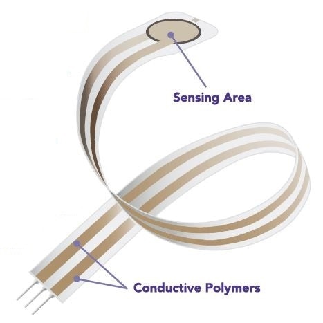
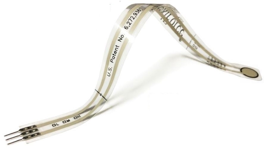
Flexible and ultra-thin printed circuits comprising of two flexible substrates (polyester film). Silver circles with traces are placed below and above a pressure-sensitive layer. Conductive polymer is applied to each layer, and then a pressure sensitive layer is applied. Adhesive is utilized to laminate the two layers of substrate.
Shunt Mode Sensors
Polymer thick-film devices comprising of two membranes divided by a thin air gap.
Membrane 1 has two sets of interlaced traces electronically isolated from each another.
Membrane 2 is coated with a special resistive and textured ink.
When force is applied in both of these sensor types, there is a decrease in resistance that is inversely proportional to the applied force.
Tekscan Manufacturers Thru Mode Sensors (AKA, FlexiForce Sensors)
Tekscan chooses to manufacture thru mode sensors due to the operational benefits and properties they provide to design engineers. To find more information on the particular differences between shunt and thru mode force sensor technology, read this article.
2. How Accurate Are They?
The easiest answer is that printed force sensors are as accurate as the application requires.
FlexiForce sensors have a high resistance (of about <2 MΩ) that decreases when loaded. In consideration of the inverse of resistance (conductance), the conductance response as a function of force is linear within the sensor’s designated force range.
The fact that they have linear conductance responses, are passive, and have a great dynamic range of resistance, assists the design engineer in utilizing simpler electronics that do not need lots of filtering.
Force vs. Resistance and Force vs. Conductance of FlexiForce Technology
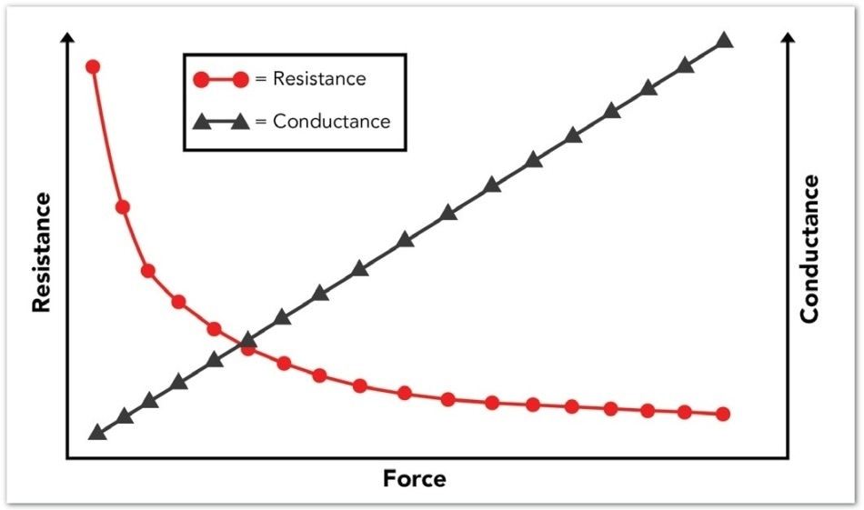
As illustrated in this graph, the conductance curve of FlexiForce technology is linear.
Comparison of Force Sensor Technologies
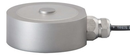
Load Cell
Pros
Cons
- Expensive Piece Price
- Heavy, Bulky Weight
- Extensive Power Requirements
- Needs Regular Factory Re-Calibration
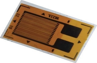
Strain Gauge
Pros
- High Precision
- Compact Size
Cons
- Integration is Expensive
- Needs Complex Circuitry (Often Requiring Third Party Outsourcing)
Microelectromechanical systems (MEMs)

Pros
- High Precision
- Compact Size
Cons
- Expensive to Purchase
- Costly Integration
- Needs Complex Circuitry (Often Requiring Third Party Outsourcing)
Printed Flexible Force Sensors
Pros
- Flexible, Thin, Form Factor
- Needs Simple Circuitry
- Minimal Power Requirements
- Easy Calibration
- Cost Efficient
- Customizable
Cons
- Not as Precise as MEMs Devices, Load Cells, or Strain Gauges
3. How Durable Are They? (Part 1)
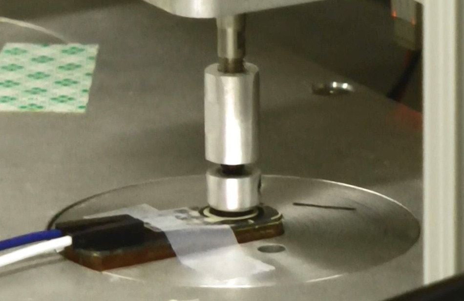
Although printed force sensor technologies are flexible and thin, they have shown the ability to maintain and withstand performance in some of the harshest operating environments, particularly in the case of FlexiForce sensors. Here is one example:
Summary: Three FlexiForce sensors (A301 (standard technology) ESS301 (enhanced stability series technology) and HT201 (high temperature technology)) were normally actuated (with no shear) with a 2.3 k (5 lb) over one million times utilizing a pneumatic air cylinder testing fixture.
Once the experiments were complete, all sensors were assessed against Tekscan’s published performance expectations for linearity error (<±3% of full scale (line drawn from 0 to 50% load)) and sensitivity changes.
Loading Profile and Schematic:
- The sensors were pre-conditioned to 120% of test load 2.7 kg (6 lb) for 20 seconds, twice
- 5up step profile to 2.3 kg (5 lb) with a 10-second dwell at each step
- 2.3 kg (5 lb) load was applied at 1 Hz, 50% duty cycle for 100,000 actuations
- 5up step profile to 2.3 kg (5 lb) with a 10-second dwell at each step
- Five minute rest with no load
- 5up step profile to 2.3 kg (5 lb) with a 10-second dwell at each step
- Steps three to seven were repeated until one million total actuations were achieved
Results
- Linearity error for all three sensor types were confined to well within <±3% of Full Scale
- All sensors did not show any signs of compromised performance or failure
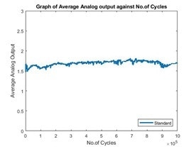
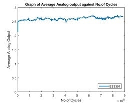
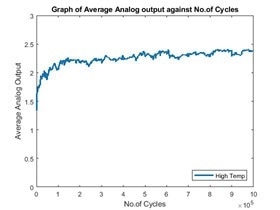
Note: There was a small increase in sensitivity observed in the durability graphs at the beginning of each test. This increase in sensitivity is a result of the viscoelastic behavior of the pressure sensitive layer within the sensor.
In applications where greater precision and accuracy are needed, correct calibration and conditioning protocols may limit this effect. Additionally, the durability performance that is seen here is dependent on the application.
3. How Durable Are They (Part 2)
The following is another third-party example to evidence the durability of FlexiForce sensors in extreme operating environments:
Summary: For 26 days (or, to a sum of 1.5 million load cycles), HT201 sensors were hydraulically loaded in testing fixtures, with the force load concentrated onto the sensor’s sensing region.
The testing fixtures were put inside a chamber that was environmentally controlled. The measured variables were sensor output voltage, applied load, ambient temperature, and test block temperature.
Loading Profile and Schematic:
- Sensor evaluation was performed over a 26-day period (or, to a total of 1.5 million load cycles) dependant on a 24-hour schedule.
- Ambient temperature was heightened from -30 °C (-22 °F) to 121 °C (250 °F) over a period of five hours.
- Temperature remained consistent at 121 °C (250 °F) for 14 hours, and then was reduced to -5 °C (22 °F)
- A cyclic load of 2,224 N (500 lbf) was applied at 1 Hz frequency.
- A load sweep was periodically performed at various temperature levels during the experiment.
- A load level was changed between 0 and 2,269 N (600 lbf) over 100 seconds.
- Measured variables included sensor output voltage, apply load, test block temperature, and ambient temperature.
- The test chamber was opened periodically to visually observe sensors for any apparent damage.
Results:
- All sensors maintained and survived performance within specifications.
- All sensors maintained positive linearity, generating output in proportion to a load level throughout sweep cycles
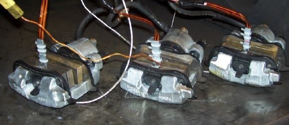
Image courtesy of Powertrain Research & Advanced Engineering (Ford Motor Company)
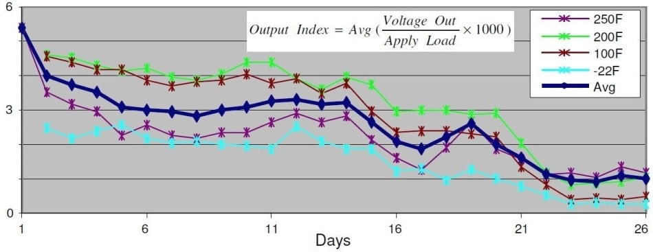
Normalized sensor output voltage at various temperatures over the 26-day period of testing.
Source: Fujii, Yuji (2009) “Characterization of Pressure Resistive Elastomer for Low-Cost Load Sensing” Powertrain Research & Advanced Engineering (Ford Motor Company); Presented at the 2009 CTI Symposium & Exhibition (May 12-14, 2009; Detroit, Mich. USA)
How Much Force Can They Measure?
Adjustable sensitivity and flexibility in circuitry selection are two of the major benefits of utilizing printed force sensors in an embedded design. FlexiForce sensors, for example, have such a great dynamic range that helps them to record much greater forces just by changing the reference voltage and/or adjusting the circuit gain.
Tekscan recommends an inverting op-amp, dual source circuit. Any circuit that provides a resistance change may be appropriate. For a full outline of maximum and standard force ranges for FlexiForce sensors, download this document.
Recommended Circuit for a FlexiForce Sensor (Inverting Op-Amp, Dual Source)
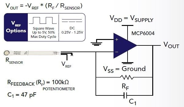
100K potentiometer and 47 pF are general recommendations; the customer’s particular sensor may be more suited to an alternative potentiometer and capacitor. Testing should be carried out to establish this.
- Supply voltages should be maintained
- Polarity of VREF must be opposite the polarity of VSUPPLY
- Sensor Resistance RS at no load is >1 MΩ
- The maximum recommended current is 2.5 mA
The Value of Adjustable Sensitivity to Capture High Forces with FlexiForce Sensors

The graph above details how a FlexiForce sensor can capture higher force ranges when the Reference Voltage or Feedback Resistor is changed. The output continues to be linear in all scenarios.
Adjustable sensitivity can be performed by employing a potentiometer, or a Digital-to-Analog Converter (DAC) to change the reference voltage.
For any particular sensor, the user can decrease or increase the measurement range by changing the reference voltage and/or feedback resistance. The graph to the left outlines this process in action. Alternatively, the sensitivity can be enhanced for the measurement of lower forces by increasing the drive voltage or resistance of the feedback resistor.
5. What Environmental Conditions Can They Withstand?
Even applications in humid and hot environments have a force-sensing solution with printed force sensors. However, this statement is most applicable to FlexiForce sensors.
Tekscan has manufactured advanced formulas for its conductive materials that maximize sensor performance for extreme humidity and temperature applications. These variations are available as standard, off-the-shelf sensors (as detailed here), and are also available for a customized sensor design.
ESS301
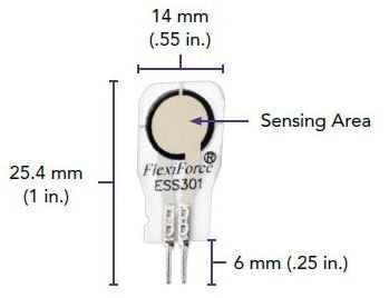
- Operating temperature: Up to 85 °C (185 °F) with relative humidity up to 95%
- Force range: 4.4 N (0 - 1 lb)
- This sensor can analyze up to 445 N (100 lb) with adjustable drive voltage (as shown on page 7)
- Linearity: < ±3% of full scale
- Repeatability: < ±2.5% of full scale
HT201
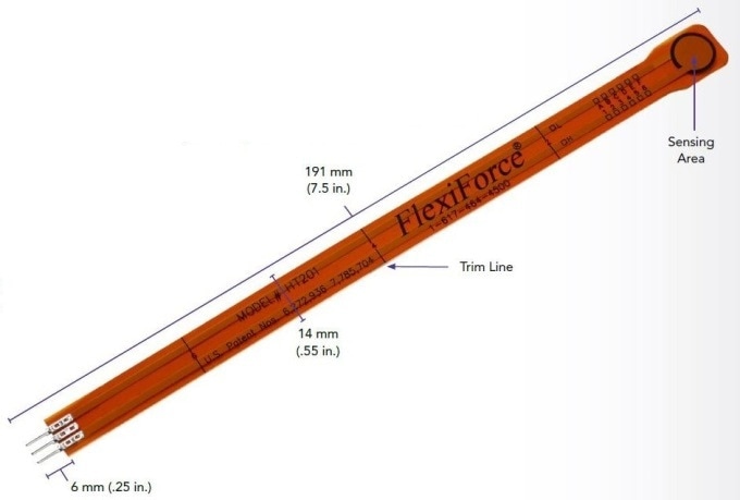
- Operating temperature: Up to 200 °C (400 °F)
- Force range: 222 N (0 - 50 lb)
- This sensor can analyze up to 2,224 N (500 lb) with adjustable drive voltage (as shown on page 7)
- Linearity: < ±3% of full scale (up to 899 N (200 lb))
- Repeatability: 3.6% of full scale
Bonus: What Are Common Uses for Printed Force Sensors?
While the applications are never ending, these are four of the most frequently used ways to employ printed force sensors in an embedded application.
- Detect and Measure Relative Change in Force or Applied Load
- Detect and Measure the Rate of Change in Force or Applied Load
- Detect Contact and/or Touch
- Identify Force Thresholds to Trigger an Action
Conclusion
Think Printed Force Sensors May be Right for Your Application? Consider FlexiForce!
Now is the time to evaluate how embedding force sensing technology into products will bring a competitive edge. The following are four questions to consider when defining the process:
- What force sensing technology can economically and effectively be integrated into the product design?
- What electrical or mechanical needs or challenges may affect the selection of force sensing technology?
- Does the product need capturing force within a particular sensitivity range?
- Is the choice of force sensor supported by a group of expert engineers with a strong history of embedding force sensing technology?
Seeking Force-Sensing Technology for Your Application? Let’s start a conversation.
Tekscan understands the difficulties that design engineers face, and the risks that are taken when embedding new technology.
Whether it’s a customized design or a standard FlexiForce sensor, Tekscan has proven experience in assisting design engineers to achieve high-value products with force sensing technology. The customer’s return on investment comes in the form of confidence in their product design, a reduced development process time, and an enhanced end-user experience.

This information has been sourced, reviewed and adapted from materials provided by Tekscan, Inc.
For more information on this source, please visit Tekscan, Inc.