In this article, the example of the catalytic reforming unit usually found in a refinery is used to demonstrate the options for using on-line analyzers to offer timely, useful, and available process stream quality data in sophisticated process control.
Refinery
Measurement Made Easy
First, the background — why the optimization of refinery process units is so familiar and so essential, and what analytical tools exist to help — must be considered. The main problem in refining is that although crude oil refining is a high-volume and continuous process with very noteworthy raw-material and energy costs, it is not steady-state. Crude oil feedstocks differ continuously in quality, cost, and availability — while refinery products and their markets are very dynamic with regards to demand, pricing, and specifications.
This results in the use of comparatively complex whole refinery linear programming (LP) models to handle these variations. Beneath these models, individual process unit Advanced Process Control (APC) packages should keep the units on target (even though these targets will change) and under control.
Process Optimization
The Refinery Naphtha Complex with CCR and Integrated Petrochemical Units
If you look at a specific area within the refinery — the so-called naphtha complex, or naphtha conversion area — you can see the interaction between several different process units and streams. The Catalytic Reformer (CCR) unit is pivotal to these process units and streams. This unit acquires low-value heavy naphtha from the CDU and converts it into a higher value high-aromatics, high-octane feedstock, after hydro-treating it.
Note: In this article, CCR is used as a standard to signify a catalytic reforming unit. The arguments presented are specifically applicable to continuous catalytic regeneration reformers, but is also applicable to fixed bed units. The questions are as follows: what alternatives might there be for naphtha processing or sources of CCR naphtha feeds, and what alternative uses exist for the different unit products?
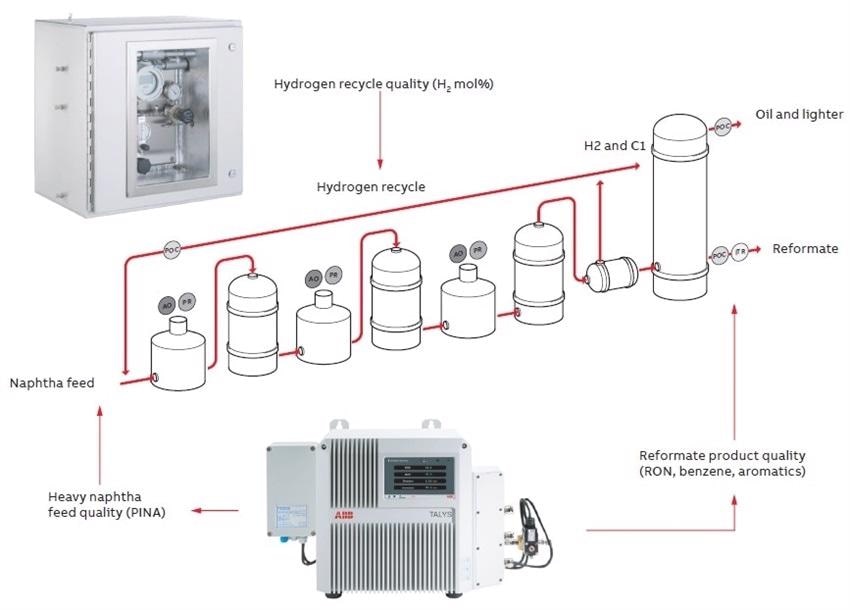
The following diagram is a simplified and idealized view of these scenarios. For instance, the reformate product from the CCR is often directed to the gasoline blending pool as a useful high-octane blend component; however, the high octane value of reformate derives from high aromatics (BTX) content.
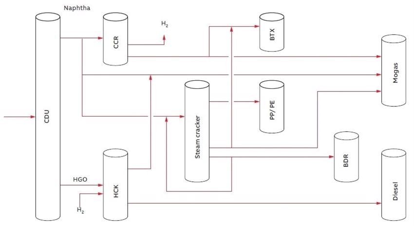
Simplified overview of naphtha conversion in a refinery context
This has different uses and, based on the price breaks between the aromatics unit and blended gasoline product, diversion as an aromatics unit feed might be determined. In the same way, the straight-run naphtha from the CDU, typically hydro-treated as CCR feed, might be better used as raw material for the naphtha steam cracker olefins unit, again based on the relative instantaneous profitability of aromatics, gasoline, and olefin products.
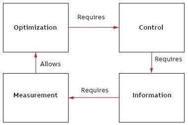
The cycle of measurement and optimization
The key to process optimization is measurement at some level. Measurement yields information, which enables the possibility of control. What form this measurement takes is a rather more open question, and a subject of great entertaining debate between those (mainly chemists) who do not trust anything which is not a directly traceable analytical result, and those (mainly engineers) who like statistics and dislike analyzers.
This results in various approaches to APC as follows.
APC based on inferential models
- Needs chemical engineering model of unit
- Requires lab test data to calibrate and maintain the inferential quality estimator
- Use of many basic mass-flow, temperature, and pressure transmitters
APC based on physical analyzers
- Requires extensive training, maintenance, calibration, and spares stockholding
- Use of several single-property physical analyzers for direct measurement
APC based on advanced analyzers
- Requires calibration or calibration model development
- Generally provides considerable improvement in reliability, precision, and speed
- Use of a smaller number of multi-stream, multi-property analyzers
Although APC based on actual process stream quality measurements from real analyzers is superficially appealing, it is full of risk.
Historically this approach was hindered by:
- Limited reliability, high life-cycle costs
- High capital cost
- Complex operational requirements (calibration, validation)
- Large infrastructural requirements for installation
Technical advances have led to:
- More durable, simpler, lower cost analyzers
- Considerably reduced installation and operational demands
- Broader range of available technologies
Here, two examples of modern, robust analyzer technologies are considered that have allowed simpler and more reliable implementation of APC strategies depending on real-time process-analytical measurement. Fourier-Transform Near IR (FT-NIR) analyzers with low life-cycle costs and long maintenance intervals have provided one way to tackle part of the issue. Chosen wisely, they provide space technology levels of reliability and uptime (quite literally since the technology is routinely used in climate sensing satellites).
On-line FT-NIR analyzers now possess an established track record in reliable hydrocarbon stream property measurement (in this case, RON and BTX in reformate product and PINA in heavy naphtha feed). The second technology is a solid-state electrochemical sensor-based technique for supervising the hydrogen recycle/net gas stream also vital in CCR operation.
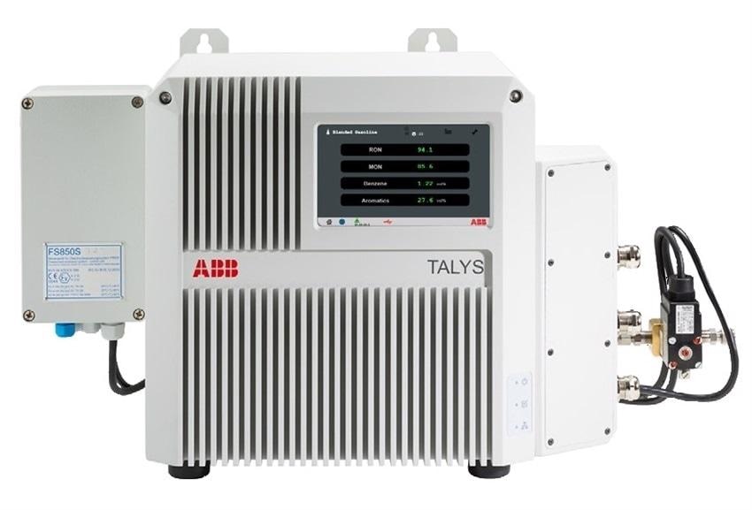
ABB Process FT-NIR analyzer TALYS ASP400-Ex
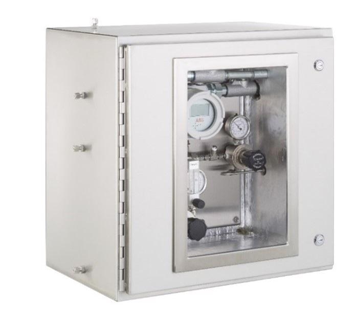
ABB Process Hydrogen Analyzer HP30
Catalytic Reforming Unit
In summary, the catalytic reforming unit, whether a CCR, as shown here, or a fixed-bed type, takes a heavy naphtha feed and, by catalytic conversion at rationally high temperatures but at moderately low operating pressure, converts the naphthenes and paraffins to mainly aromatics.
The resulting product is a aromatics-rich reformate stream, and a hydrogen net gas is produced within the unit and partially recycled.
What problems and choices exist for the operation of this unit? As mentioned earlier, the product of the CCR unit is not just a potential blend-stock for gasoline blending. This is the conventional key product, but with varying markets, and more complex refineries with extensive heavy oil up-conversion, the previously seen CCR byproducts have now become important and potentially attractive economic choices.
Reforming converts heavy naphtha into:
- High-aromatics (BTX) feed for petrochemicals
- High-octane feedstock for gasoline blending
- High-purity hydrogen appropriate for use as hydrocracker make-up gas
CCR unit operation provides an astoundingly huge number of degrees of freedom including severity vs. pressure vs. selectivity, which can all be traded off to:
- Run for maximum BTX yield
- Run for maximum octane barrels
- Run for maximum catalyst lifetime
- Run for maximum Net Gas
- Run for minimum energy usage
The key operating parameters for the unit will be pressure, severity, catalyst bed temperatures, and profiles, which are interlinked and concurrently affect octane number, yield, BTX spread, and aromatics content along with net hydrogen make.
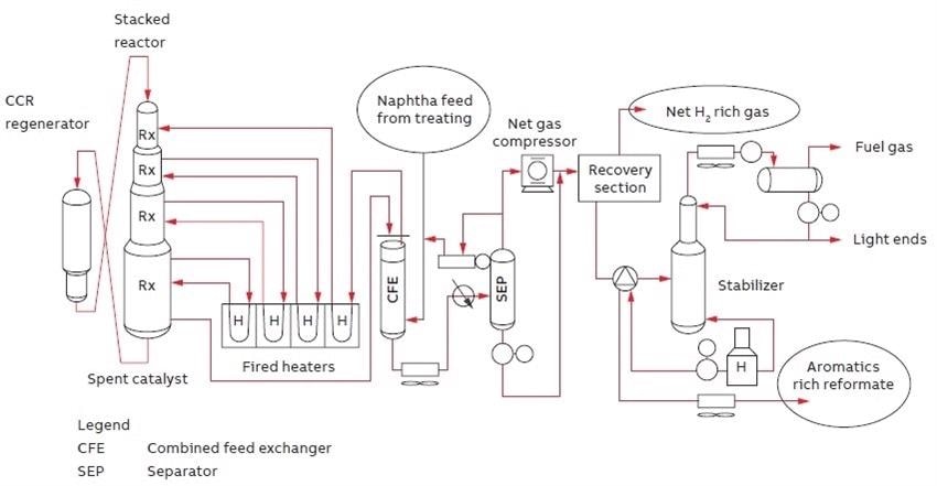
Typical UOP CCR platforming process unit
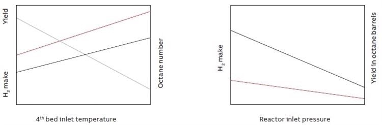
Example operating parameter trade-offs in CCR operation
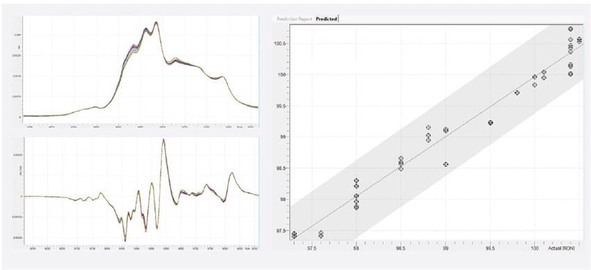
Calibration dataset, 1st derivative, and PLS regression plot for RON
On-line FT-NIR vs. Lab Test Method RON
The most fundamental measurement is octane number monitoring (usually RON) of the reformate product stream which is an indicator of reactor severity, and to this measurement, you can easily add discrete components such as toluene percentage, xylenes percentage, and benzene percentage, or chemical compositional parameters such as total aromatics percentage.
For example, a typical RON and aromatics modeling data set, and also the resulting RON calibration model, is shown.
It is to be noted that the model accuracy (vs lab test) at approximately 0.2 RON at 1 sigma is better than the ASTM standard method reproducibility (R) owing to good site laboratory precision. Thus, the on-line FTIR does a better job than an on-line CFR engine would, which would, in any case, be considerably more expensive overall.
This is the main advantage of sophisticated solid-state or optical devices for process stream quality analysis: better, cheaper, and faster data.
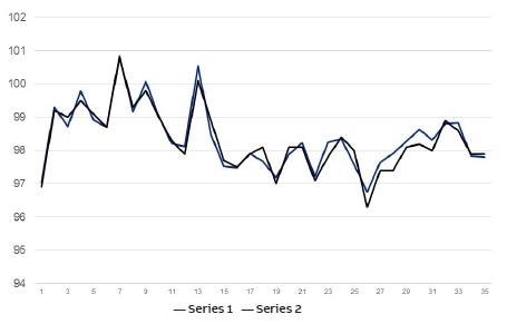
Example validation plot of on-line FT-NIR RON data (Series 1) vs lab test samples (Series 2)
Naphtha Feed
The heavy naphtha feed is the second stream analysis, which may be measured using the same FTIR unit as the one used for the reformate product. Here, distillation and PINA are the target properties, which considerably affect the CCR unit yield and selectivity.
Naphtha quality variations can result from varying CDU feedstocks and operation as well as from alternative naphtha feed sources. Where CCR units are run to have excess catalyst regeneration capacity, sub-optimum heavy naphtha feeds (for instance – from the FCC unit) can be combined or run with traditional straight-run naphtha, leading to a much more dynamic unit envelope.
The net gas/hydrogen recycle stream is studied for the final measurement in this set of real-time on-line process analyses for unit optimization. Here, the main parameter is simply H2 mol %, but it needs to be measured in the context of a varying background of mixed light hydrocarbons content. Certainly, the net gas recycle stream is not pure hydrogen. It is combined with other light gases recovered in the separator/recovery stages.
This is a major challenge for traditional technologies such as thermal conductivity detection (TCD) that can only deal with a restricted number of interfering components (no more than two). The solid-state sensor is specific in response to hydrogen and is also protected against potential contaminants such as CO and H2S by a diffusion membrane, therefore enabling rapid hydrogen transport while blocking larger contaminant species.
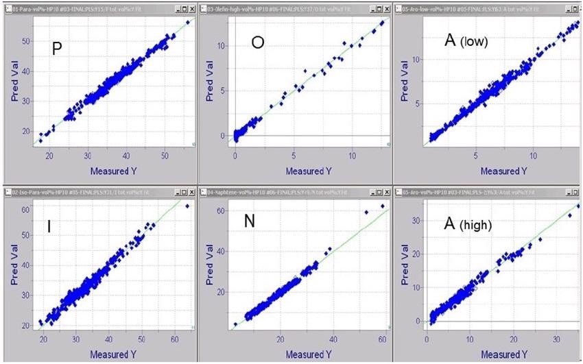
PLS regression calibration plots for PIONA in Naphtha Feed
Summary
This article has reviewed the use of simple and robust yet advanced process analyzer technologies, particularly FT-NIR and solid-state sensor-based hydrogen detection, in the most vital process unit streams in the catalytic reforming unit. It is mentioned that the aromatics, octane, PINA, and hydrogen measurements can be made using these pretty simple analytical methods, and that this data is reported in almost real-time (one minute stream cycle time), enabling close integration with unit advanced process control.
This enables better management of unit operational parameters, with a vision to optimizing the production of high-quality reformate and net gas/hydrogen, with yields and composition better aligned with overall refinery and product market demands.
References
- Mohaddecy, S.R.S; Sadighi, S.; Bahmani, M.; “Optimization of Catalyst Distribution in the Catalytic Naphtha Reformer of Tehran Refinery,” Petroleum & Coal 50 (2), 60–68, 2008.
- Taskar, M.U.; “Modelling and Optimization of a Catalytic Naphtha Reformer” PhD Dissertation, Texas Tech University, USA, May 1996.
- Kavousi, K.; Mokhtarian, N.; “Simulation of the CCR Unit of Isfahan Refinery with PETROSIM Software,” International Science & Investigation Journal 4 (3), 14–33, 2015.
- Poparad, A.; Ellis, B.; Glover, B.; Metro, S.; “Reforming Solutions for Improved Profits in an Up-Down World,” UOP LLC, a Honeywell Company, Des Plaines, Illinois, USA, 2011.
- Robert A. Meyers, Handbook of Petroleum Refining Processes, Third Edition, 2004.
- Chapter 4.1 – UOP Platforming Process.

This information has been sourced, reviewed and adapted from materials provided by ABB Level Measurement Products.
For more information on this source, please visit ABB Level Measurement Products.