Near-infrared light is the range of electromagnetic wavelengths between around 700 nanometers (nm) and 1500 nm and is not visible to the human eye.
This makes it perfect for an increasing amount of 3D sensing applications, for example, iris scanning, facial recognition, terrain mapping, gesture recognition, night-vision security cameras, and automobile LiDAR.
3D imaging and sensing combined is estimated to become an $18.5 billion market by 2023, with far-reaching applications in the scientific, consumer electronics, law enforcement or security, defense or space, medical, automotive, and industrial or commercial sectors.1
NIR Facial Recognition
Facial recognition is one of the most discussed uses of 3D NIR sensing technology.
Multiple models of smartphones have been launched in the last 18 months that contain this feature as a type of biometric security, enabling the user to unlock their phone just by looking at it.
Two-dimensional image-based facial recognition systems utilize algorithms in order to evaluate photographic images to match facial features and these have been around for some time.
One benefit of NIR-based sensing systems is that they are not influenced by various ambient lighting conditions, and can carry out successful identification from varied angles, for example a profile view.
These systems have the ability to sense 3D objects by directing NIR light in a dot or grid pattern towards an object (such as a human face). A diffractive optical element (DOE) is commonly utilized to refract an NIR light beam into a dot pattern.
The pattern is captured by a NIR camera after being reflected from the object and back towards the device.
Algorithms then evaluate the reflected data for any deviation from the first grid pattern, producing a 3D ‘map’ of facial characteristics, which can be matched against stored data to verify the identity of the user.
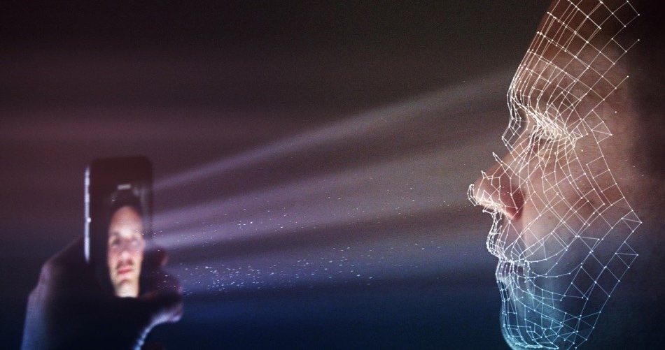
Illustration of smart phone facial recognition, where an NIR structured light pattern is projected towards a person’s face, reflecting off the contours of their features to create a 3D image.
Quality Considerations for NIR Sensing Systems
NIR emissions for 3D sensing applications are frequently generated by lasers and LEDs (light-emitting diodes).
With the fast adoption of sensing systems comes an increasing demand for successful techniques that measure the performance, accuracy, and quality of NIR emitters.
NIR systems can be prone to issues with performance, for example, low-output, poorly-placed emission points, and inconsistent intensity.
While NIR wavelengths cannot be seen by humans, they can still enter the eye. If exposure is prolonged, it can result in damage to the cornea or retina.
NIR devices, particularly those employed for eye detection and facial recognition, must be thoroughly designed and tested to make sure that they are emitting safe levels of intensity.
A measurement system must address the 810 to 960 nm range, common for NIR sources utilized in these applications, in order to qualify emissions used for facial recognition.
A measurement system ideally acquires a range of different features for example maximum power or intensity, emission uniformity, emission distribution, radiant flux, or spatial position. It should also measure these features throughout the entire distribution area.
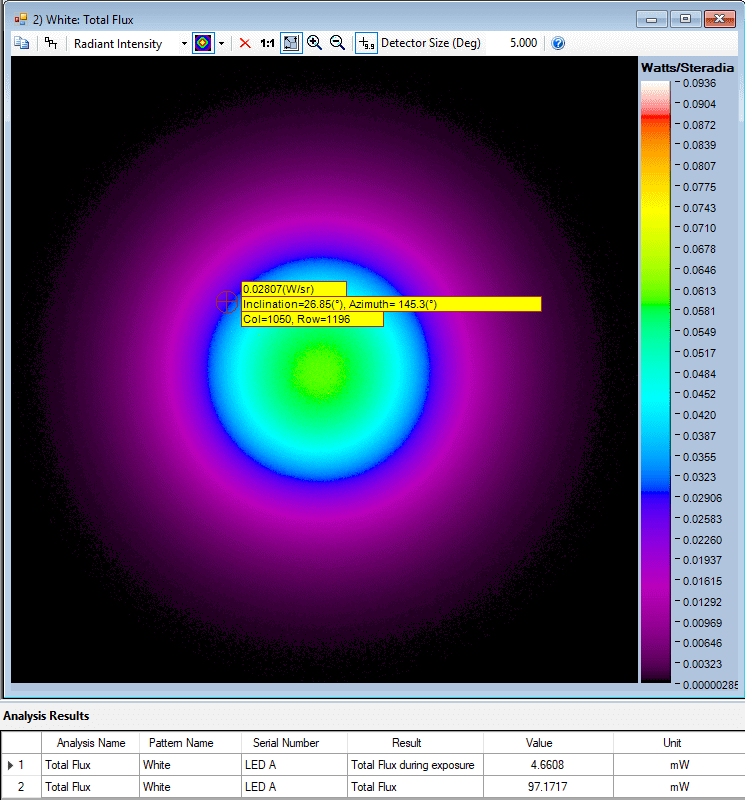
Example of a Total Flux analysis of an NIR LED over angular space, shown in a false-color scale using Radiant’s NIR Intensity Lens and TrueTest™ radiometric light measurement software. Radiant flux is a measure of radiant energy emitted per unit of time, e.g., Watts (joules per second).
Challenges of Testing NIR Emitters
Along with the quality considerations outlined above, facial recognition systems display a further challenge for the evaluation of NIR performance.
The acquisition of NIR light in an angular space is very challenging for conventional measuring equipment, particularly when identifying up to 30,000 emission points created by the smart device DOEs of today.
Utilizing image-based NIR measurement systems (such as a radiometric camera like Radiant’s ProMetric® Y16 Imaging Radiometer) for NIR source measurement can reduce this difficulty by capturing and evaluating all emission points generated by a DOE throughout a large spatial area.
To evaluate the whole emission area that will cover a face, the testing device must capture and analyze a large angular distribution quickly and at close range.
A wide-angle scope is necessary in order to achieve this because the NIR-emitting device is normally positioned at a close distance (for example the user holding a smartphone in their hand).
Similar to any source of light, an NIR light emits light in three-dimensional angular space. Each dot in a DOE pattern may be different in terms of position or intensity based on the emission angle.
The measurement of the NIR DOE pattern must be carried out at every emission angle to make sure that DOE patterns are correctly projected and that each dot has adequate intensity to be received and properly interpreted by NIR sensor of the device.
Angular Measurement Solutions
To assess the intensity of NIR emissions throughout angular space, a device manufacturer can utilize a goniometric measurement system.
A goniometer rotates an NIR light source in front of a camera or photodetector to take two-dimensional images of emissions at every angle. This technique takes a lot of time and needs thousands of rotations to acquire a full angular measurement.
Gaps in measurement may occur between goniometric rotations, which means deviations in NIR intensity at particular points may be missed.
As NIR emissions can be harmful to human vision, if any angular data point throughout goniometric measurement is missed, it may also mean that an abnormally strong emission is missed which could be dangerous to the user, particularly over time.
A camera used in combination with Fourier optics is an alternative to goniometers, which omit the requirement for device rotation by capturing angular emission data from only one point.
Lenses created utilizing Fourier optics concepts allow connected imagers to distinguish the complete angular distribution of a light source, leaving no measurement gaps.
Advanced NIR measurement systems for example Radiant’s NIR Intensity Lens solution can identify radiant intensity (strength, measured in Watts per steradian, or W/sr) of a complete NIR light source distribution in 3D space (to ±70°), establishing irregularities, hot spots, peak emission, and further issues.
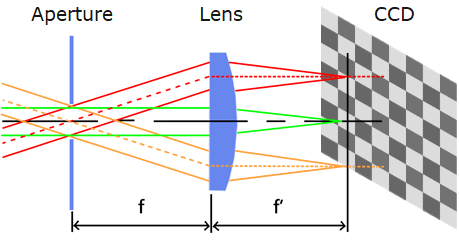
Illustration of Fourier optics directing angular emissions of light through the specialized lens onto points on an imaging system’s sensor, forming a 2D polar plot of the 3D distribution.
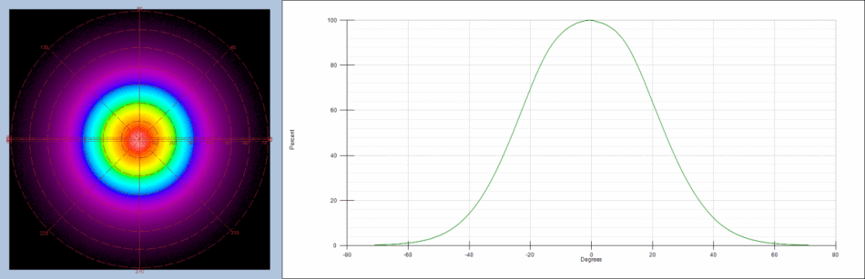
Radar plot and cross-section showing radiant intensity (as a function of angle) of an infrared LED. The Fourier-optic lens is calibrated to its connected imaging system, allowing it to accurately map angular emissions of the NIR device to ±70° at once.
DOE Measurement Challenges
When analyzing NIR DOE emissions for facial recognition it is crucial to evaluate every single dot for accuracy and performance.
The technique for analyzing DOE emissions until recently was restricted to verifying dot patterns for accuracy by mapping them against ideal coordinates or patterns (normally with the NIR light pattern cast against a wall or screen).
This technique is reliant upon a static pattern match and does not flexibly adapt to recent DOE patterns.
This technique also cannot document accurate radiometric data of the DOE emission points, offering only dimensional analysis and a basic pass/fail evaluation.
Every dot in a facial recognition DOE array must be precisely positioned (inclination, azimuth, angle) and emitted with the accurate radiant intensity to guarantee that it is correctly reflected back and registered by the infrared sensor of the device.
Manufacturers must manage the output and position of every dot for the device to effectively map facial contours.
For a stringent assessment of dot-by-dot performance, the most effective system should determine points of interest throughout the image, quantify values for every dot in the DOE pattern, and investigate the precision of the total pattern.
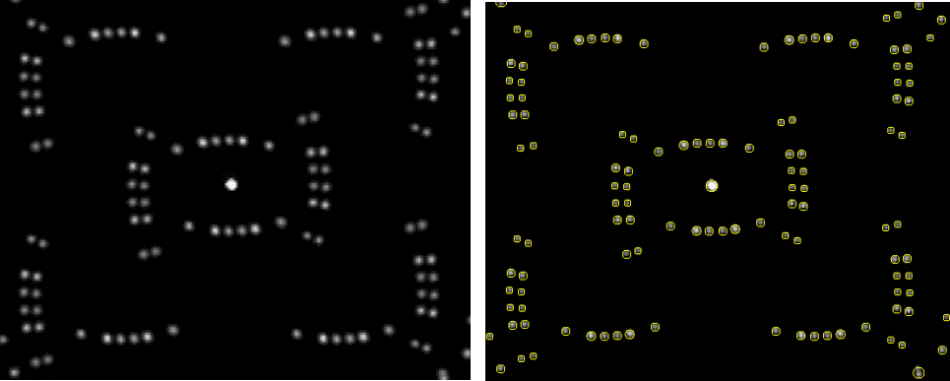
A sample DOE dot pattern before (left) and after analysis (right) using automatic dot detection in Radiant’s TrueTest™ Software. The software measures maximum peak (strongest emitter), maximum peak location (inclination/azimuth), maximum peak averages, maximum peak solid angle, number of pixels as maximum peak point, spot power uniformity (between dots), total flux, and DOE flux, along with dot-by-dot measurements for comprehensive analysis.
NIR Measurement – See It in Action
The SPIE Photonics West conference is happening in San Francisco from February 3rd to 7th to provide an opportunity to learn more about the most recent news in NIR technology and its applications.
Come and see Radiant during the Photonics West Exposition (booth #3113), where there will be demonstrations of Radiant’s NIR Intensity Lens solution and the AR/VR Lens solution, a specifically created lens solution for near-eye display testing within virtual and augmented reality headsets.
Acknowledgments
Produced from materials originally authored by Anne Corning from Radiant Vision Systems.
References and Further Reading
1. 3D Imaging & Sensing 2018, report by Yole Développement, March 2018.

This information has been sourced, reviewed and adapted from materials provided by Konica Minolta Sensing Americas.
For more information on this source, please visit Konica Minolta Sensing Americas.