Image Credit: FLIR Systems
Increasing availability of powerful, compact single-board computers is helping to facilitate exciting new product designs. This is especially beneficial for applications where miniaturization has the potential to improve efficiency and/or cost-effectiveness.
Vision systems offer the ability to leverage fully-featured board-level machine vision cameras, further reducing a product’s overall size while simultaneously providing operational flexibility, even when supporting non-standard or custom optics.
Common applications include metrology, handheld scanners, medical diagnostics, embedded vision, robotics, packaging and print inspection, benchtop labs and other systems where space may be limited.
This article explores a number of factors that should be considered when selecting an embedded vision camera; these include feature set, form factor, physical footprint, interfaces, lens mounting, software support, thermal management and also electromagnetic compatibility.
Form Factor and Feature Set
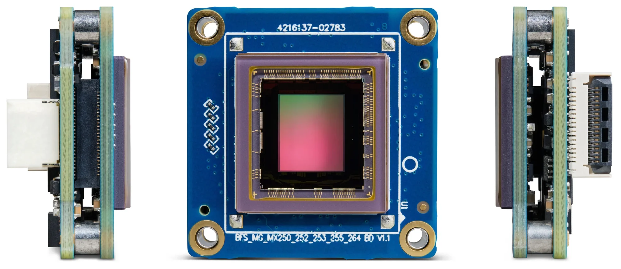
Image Credit: FLIR Systems
When moving from cased to board-level cameras, system designers are advised to carefully consider their camera and imaging performance needs. A significant number of small board-level cameras will only support low resolution sensors, a handful of GPIO lines and a restricted number of on-camera features.
Board-level versions of a number of full-featured machine vision cameras are essentially standard cameras without cases, and while these cameras may offer the imaging performance necessary for an application, they may not be much more compact than models in standard cases.
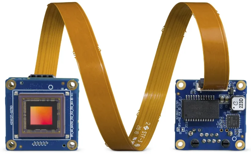
These cameras tend to utilize standard GPIO and interface connectors which are bulky and not well suited for use in embedded applications; for example, common industrial locking connectors alone are approximately the same size as a whole Blackfly S board-level camera.
The Blackfly S board-level camera from FLIR has been designed with suitability for use in embedded systems at its core.
The camera delivers the same rich feature-set, and imaging performance found on cased Blackfly S models in an extremely compact 29 mm x 29 mm x 10 mm form factor. Compact GPIO and interface connectors also afford the user additional space savings.
Another major advantage of FLIR’s embedded vision camera range is the availability of an identical form factor on all cameras, with sensors ranging from 1/3 ” to 1.1 ”. Maintaining a consistent form factor across various camera models significantly increases the ease of developing and upgrading future product variants and systems.
Lens Mounting
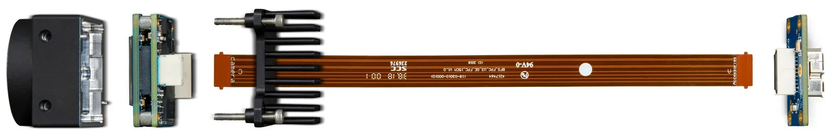
Image Credit: FLIR Systems
Board-level cameras offer an appealing alternative for customers seeking to integrate non-standard optics or looking to situate the image sensor as close to the target as possible.
Board-level cameras also allow designers the freedom to select optics outside of the standard C, CS or S-Mount lenses frequently employed in the machine vision industry. This is due to the fact that they have no fixed lens mount.
This design is also highly suitable for biotechnology and laser beam profiling because these are applications that generally do not use any lens at all.
Another frequent use of a board-level camera involves enabling the lens mount to be integrated into a different product part - hence the term ‘embedded vision camera.’
Molding a lens mound directly into a product’s housing has the potential to further reduce costs by making manufacturing and assembly more straightforward. A mount accessory can be purchased in order to evaluate a board-level camera that does not ship with a lens mount.
Cased models with identical features and sensors to board-level models can be used as development platforms, should these be available.
The size of the sensor is one of the most important factors to consider when choosing the right lens mount option for a board-level camera. S-mount lenses are generally designed to be used with 1/3 " sensors or smaller, with lower resolutions, often less than 2 MP.
Conversely, CS-mount lenses are designed to work with sensors between 1/3 ” to ½.” It is advisable to use a C-mount lens if the sensor is ½ ” or bigger.
Thermal Management
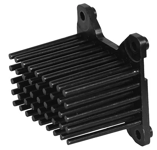
Image Credit: FLIR Systems
Cased machine vision cameras are reliant on their cases’ surface area to dissipate any heat generated by the sensor, FPGA and related components.
Where there is no case, high performance board-level cameras may require additional design adjustments to ensure that they are functioning within their recommended temperature range. Adequate heatsinking is essential in these circumstances.
Manufacturers will generally provide a maximum junction temperature for the highest temperature component - on FLIR Blackfly S cameras. For example, the maximum junction temperature of the FPGA is defined as 105 °C (221 Fahrenheit).
It is important that system designers ensure their thermal management solution meets this guideline.
The size of the heatsink, the type of active cooler required, or the surface area of the chassis the camera is mounted to will largely depend on the sensor, the operating environment, the frame rate and the amount of on-camera image processing being performed.
Thermal pastes are recommended over thermal pads when attaching the heatsink on the camera in order to minimize board stress on the camera itself.
Case Design and Rapid Prototyping
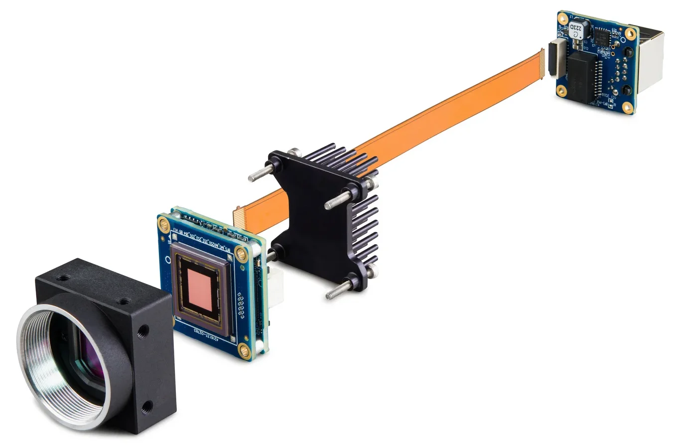
Image Credit: FLIR Systems
In most instances, board-level cameras will be integrated directly into an embedded vision system or product, meaning that a case is not needed.
In applications where the camera will not be integrated into a specific product, however, camera internals may be left exposed to the elements, and a case may be required to prevent any damage to the camera.
When undertaking rapid prototyping, embedded system designers can design and print a suitable case for the camera using 3D printers. Generic plastic cases are also available, and these can be used to encapsulate the camera and mount this in place using mounting brackets and spacers.
Interfaces and Connectors
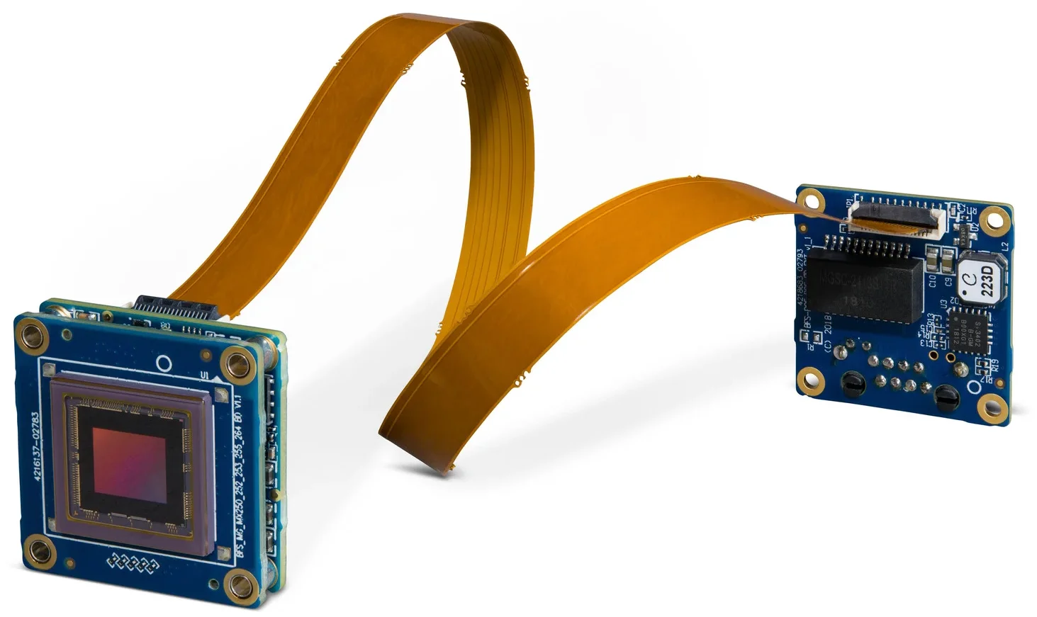
Image Credit: FLIR Systems
The USB 3.1 Gen 1 interface is ideal for embedded systems. Its relative omnipresence ensures support across a wide, varied range of hardware, including desktop PCs and ARM-based single board computers (SBCs).
Direct Memory Access (DMA) ensures that latency is kept to a minimum without requiring filter drivers. USB 3.1 Gen 1 provides power as well as up to 480 Mbytes/Sec of data throughput over one cable, therefore simplifying electrical and mechanical design.
Embedded system designers will often work to miniaturize existing designs, and in these instances, the maximum cable length is far less critical than the overall volume of the cable and connector.
Flexible Printed Circuit (FPC) cables are able to support USB 3.1 Gen 1 over cable lengths of up to 30 m while offering sufficient flexibility to fit inside already tightly packed systems. High quality locking connectors and shielded FPC cables with locking tabs can also be used to ensure a reliable, highly secure connection.
One potential downside to using the USB 3.1 interface is that it is a high frequency signal with the potential to cause interference on wireless devices up to 5 GHz; for example, GPS signal. FLIR board-level cameras with GigE interfaces are available for applications that require these wireless frequencies.
MIPI CSI is a common interface on many embedded boards, but the complexity of the MIPI protocol and its related drivers can result in development being more time consuming than USB.
Low Voltage Differential Signalling (LVDS) based interfaces are available and these are designed to directly interface with a host-side FPGA, but each channel of signal transmission necessitates the use of two wires – a minor but potentially important disadvantage in some applications.
Software Support
Software support should not be overlooked when choosing a camera for use as part of an embedded system. An SDK with support for both embedded and desktop systems provides designers with the freedom to develop vision applications on familiar tools before deploying these to the embedded platform of their choice.
FLIR’s Spinnaker SDK includes support for desktop Windows and Linux on x86, x64 and ARM based systems.
Electromagnetic Compatibility
The Electromagnetic Compatibility (EMC) of board-level cameras will be different than cased models due to the absence of shielding provided by the case.
Every cased machine vision camera from FLIR is EMC certified, but board-level cameras are not. Because board-level cameras are ultimately embedded into other products or systems, the final product must be certified separately.
Regardless of the application in question, it is recommended that best practices for electromagnetic interference (EMI) management be followed, as with any other electrical component.
Conclusion
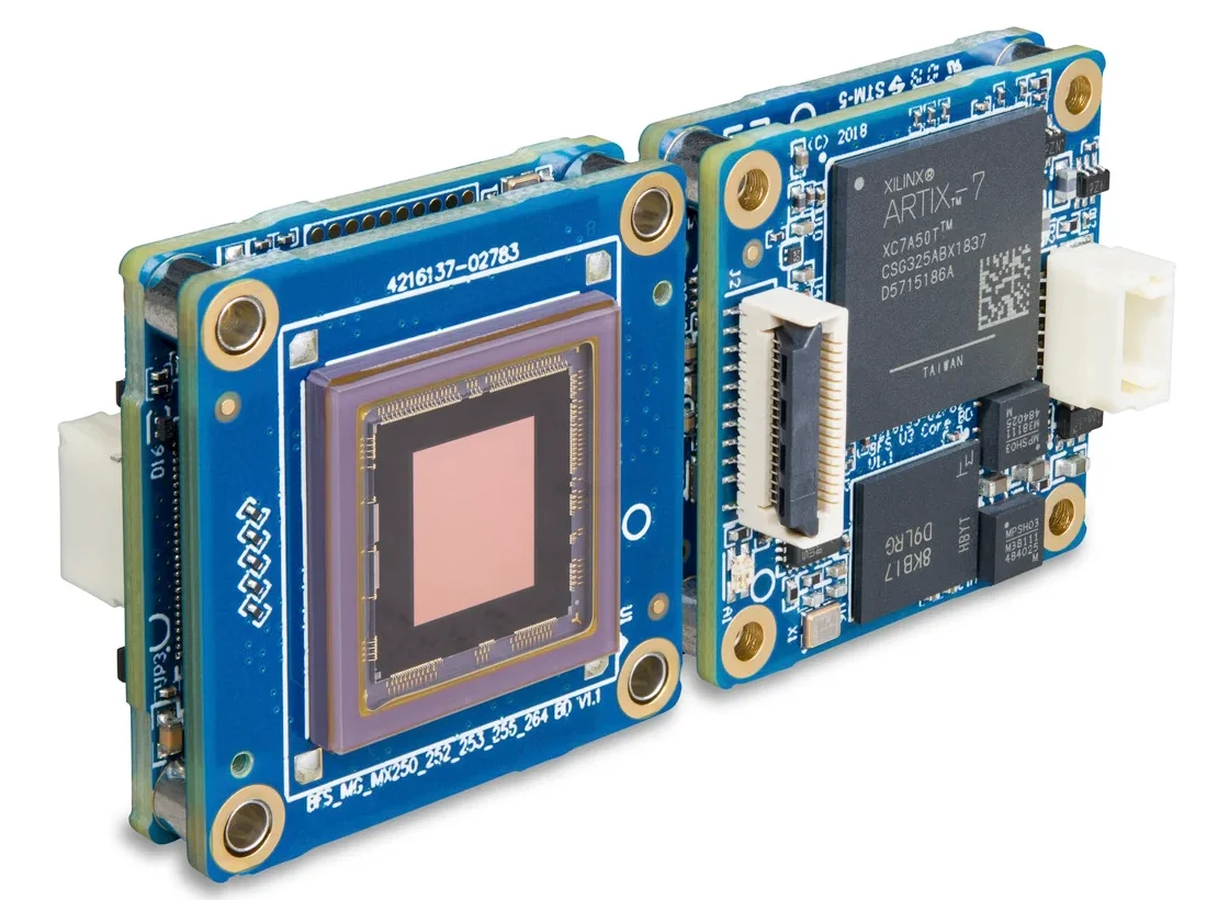
Image Credit: FLIR Systems
Current generations of board-level cameras are revolutionizing embedded vision systems, offering designers the flexibility and freedom to develop innovative, compact and versatile products.
As well as the factors covered outlined here, it is also essential to consider futureproofing any embedded system via the use of high quality sensors, optics and other reliable components.
FLIR’s whole range of board-level cameras has been designed from the ground up with these applications in mind. All the cameras come with an industry leading three year warranty, and FLIR’s machine vision experts can help designers to select the right form factor and level of imaging performance for any embedded system.

This information has been sourced, reviewed and adapted from materials provided by FLIR Systems.
For more information on this source, please visit FLIR Systems.