Efficiency is Vital on the Integration Journey
As the “drivers” of innovation, engineers are dependent on their instincts and experience to make key choices on their design journey.
However, the choices made early in the design process can have a significant impact, especially when incorporating sensing technologies, like FlexiForce™ sensors, into their design.
While each journey a device takes, from concept to completion, is unique, there are six main phases to sensor integration that act as checkpoints en route to finalization:
- Sensor characterization
- Proof-of-concept
- Prototyping
- Field testing
- Final embedded device
- Transfer to production
This article offers a real-world description of a design team that experienced these six stages when integrating a FlexiForce sensor into a smart, compact, electronic device. Please pay attention to the choices made and lessons learned through the integration process, as they provide key navigation insights into the design journey.
What are Flexiforce Sensors?
FlexiForce tactile force sensors are ultra-thin and flexible printed circuits, which can be integrated easily into force measurement applications. They are typically used to measure the force between any two surfaces.
FlexiForce sensors are perfect for OEM products due to Tekscan’s capacity to customize for an application’s particular needs:
- Geometry: FlexiForce sensors can be designed in various shapes and sizes to meet any application and product’s exact needs.
- Ink technology: Tekscan supplies three pressure-sensitive ink variations: standard, enhanced and high temperature.
- Integration support: Tekscan’s team of mechanical, electrical and application engineers possess vast experience assisting design engineers in helping them realize successful product integration
Benefits of a Flexiforce Sensor
In an electrical circuit, FlexiForce sensors serve as a force sensing resistor. When the force sensor is unloaded, its resistance is extremely high. When force is applied to the sensor, this resistance is reduced. Any changes in resistance can be customized depending on application requirements.
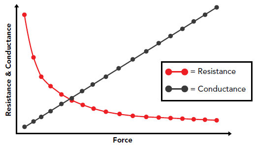
Image Credit: Tekscan, Inc.
Thin & Flexible
- Paper-thin construction
- Unobtrusive; can be embedded in small spaces
Durable
- High temperature options available (up to 204 °C)
- Works in most operating environments
Low Power
- More energy efficient than other alternatives
- Only simple electronics needed
Variety
- Customizable solutions
- Various standard sensor sizes are available

Image Credit: Tekscan, Inc.
Device Summary:
When developing a next-generation, automated, wearable, drug-delivery pump, a design team faced the challenge of incorporating a method to monitor potential blockages that could take place within the pump’s delivery system.
This demanded a force-sensing technology that could not only sense any corresponding expansions within the device but also be able to fit in an extremely tight form factor within a small pump and not lead to any significant burden issues on the device’s battery life.
After conducting the necessary research, the design team discovered FlexiForce sensors, a thin, piezoresistive force-sensing technology that provides a flexible form factor to fit into wafer-thin spaces.
The team acquired FlexiForce sensors from Tekscan’s online store – taking their first step into the sensor integration process.
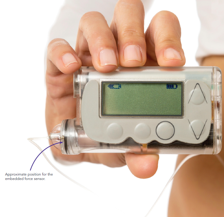
Image Credit: Tekscan, Inc.
Phase 1: Sensor Characterization
The Sensor Characterization Design phase is a key process when determining and understanding the basic functionality of the sensor technology – in this case, FlexiForce sensors.
This is a critical element of the integration process as it provides engineers and designers with the following information and data:
- A foundational understanding of sensor function in an ideal, controlled loading environment
- Quantifiable data on sensor interface configurations (interfacing materials, circuits, etc.)
- A topline understanding of sensor linearity, drift, hysteresis and repeatability via pre-programmed loading profiles
- An introduction to sensor calibration via the correlation of sensor output to known loads.
Throughout this phase, engineers and designers seek to answer the following questions:
- What is the fundamental performance of a FlexiForce sensor?
- How does a FlexiForce sensor perform with the circuits and material interfaces that are being considered for the application?

Image Credit: Tekscan, Inc.
The engineers required a sensor characterization schematic. However, rather than constructing a loading fixture and producing circuits from scratch to streamline this process, they instead turned to the FlexiForce Sensor Characterization Kit (Figure 1).
The Kit includes:
- Four (4) FlexiForce A301 sensors
- Open-source software
- A linear actuator loading fixture
- A 454 g (1 lb.) load cell, positioned below the loading platform of the fixture
- Three (3) analog circuit modules, including:
- Voltage divider
- Inverting op-amp circuit
- Non-inverting op-amp circuit
The engineers started by loading the FlexiForce sensor to the circuit and applying the anticipated force and frequency to the sensor. They then observed the raw sensor output from the Microview interface.
To their amazement, the team discovered that the sensor output varied across the various circuit types and also when loading with various interfacing materials. After several rounds of testing, the decision was made to go with a voltage divider (Figure 2).
A calibrated load cell is incorporated into the loading fixture of the FlexiForce Sensor Characterization Kit, offering an experimental control for comparison against FlexiForce sensor output.
This is a key element to characterization, as it gives users the capability of understanding the sensor’s capacity and performance under known loads. This data will prove invaluable in later design phases, as it supplies a known baseline for performance that can be a reference guide when troubleshooting or debugging.
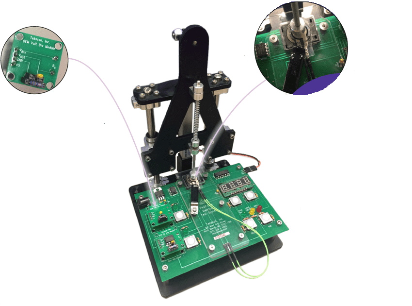
Figure 1. The FlexiForce Sensor Characterization Kit. Image Credit: Tekscan, Inc.
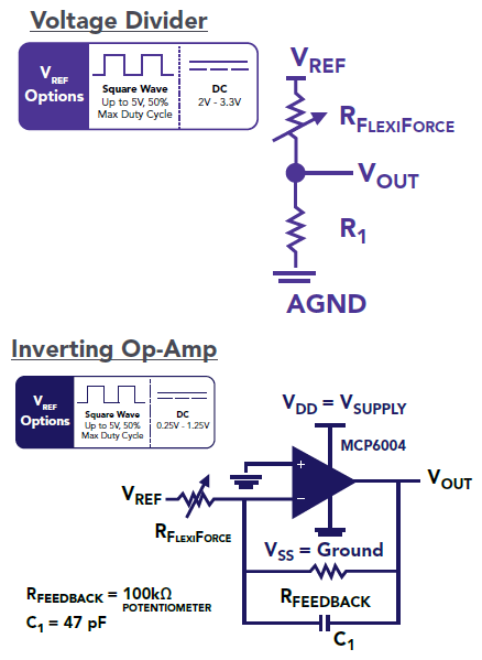
Figure 2. The FlexiForce Characterization Kit allows for interchangeable analog circuit modules, such as the Voltage Divider shown here. Inverting and non-inverting op-amp circuit modules are also included with the kit. Image Credit: Tekscan, Inc.
Phase 2: Proof-of-Concept
After characterizing sensor performance and establishing the desired circuit and interface materials, the Proof-of-Concept phase is where engineers and designers establish the application feasibility of their sensor configuration.
Throughout this phase, engineers and designers have to decide whether it is possible to capture the intended measurement successfully with the FlexiForce sensor and the electrical/mechanical configuration chosen in a “one-off” representative mock-up of the application.
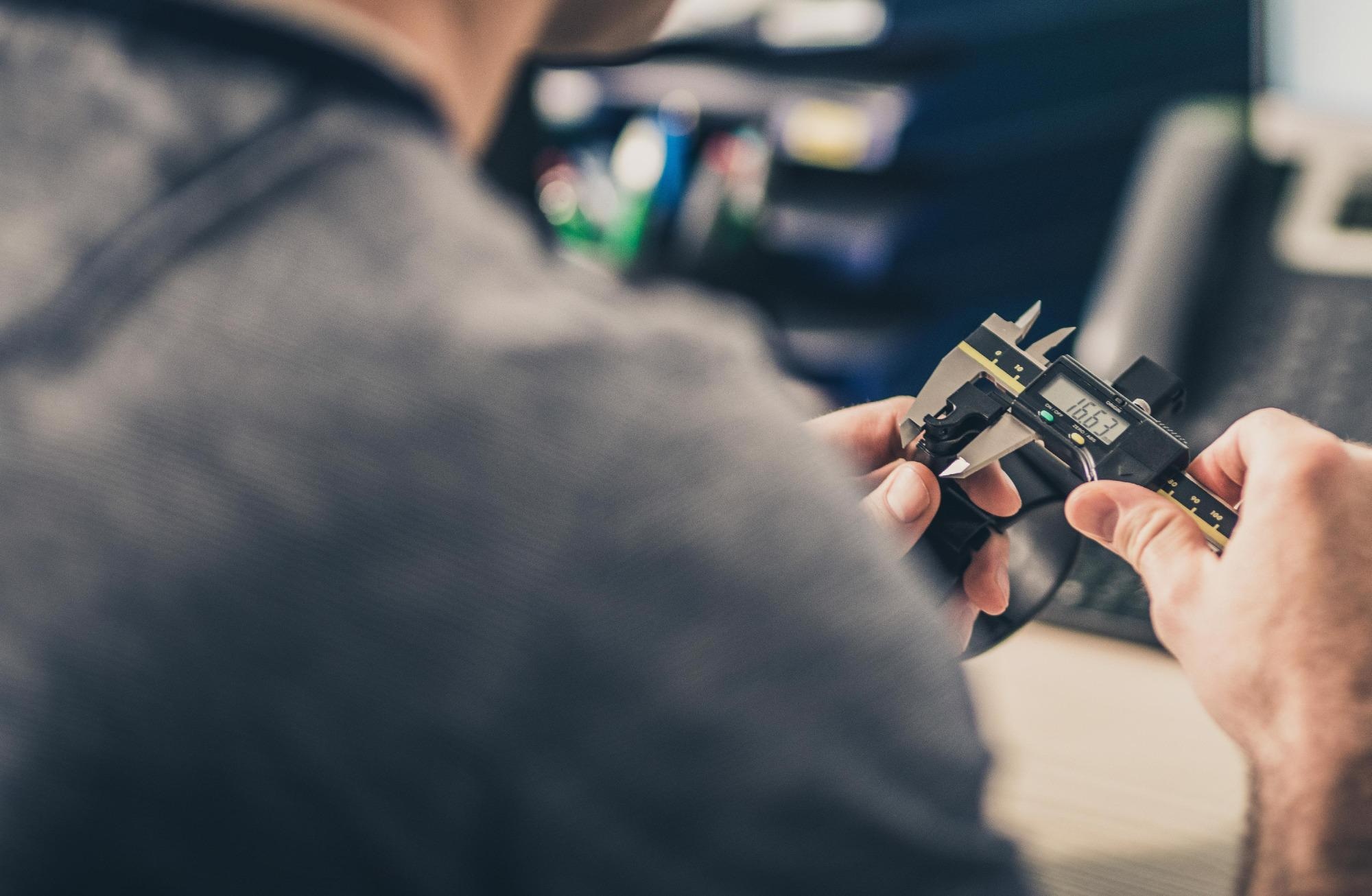
Image Credit: Tekscan, Inc.
The planned use of the FlexiForce sensor in this application was occlusion detection in an insulin pump.
The design team prepared a concept with the FlexiForce sensor positioned below a plastic tube (Figure 3), similar to the material that would be incorporated into the final design. With the assistance of the FlexiForce Prototyping Kit (Figure 4), the engineers could, in effect, test the sensor in their concept using:
- A voltage divider analog circuit module that they selected during the characterization phase
- A polycarbonate load concentrator
- Open-source software, which allowed the designers to monitor live force feedback
Yet, the design team soon realized that the current reference voltage of the circuit was not supplying enough sensitivity to obtain a robust measurement of the occlusion event. However, it was relatively easy to adjust the reference voltage from 0.5 V to 1.0 V utilizing the jumper on the board of the FlexiForce Prototyping Kit.
This increase in reference voltage gave the increased sensitivity and resolution to accurately capture occlusion in the tube. After further testing, the team established that the polycarbonate concentrator was also not delivering the desired output, so they opted for a stainless steel substrate for their concentrator.
Now that the concept was proven, the team was ready to proceed to the next design phase.
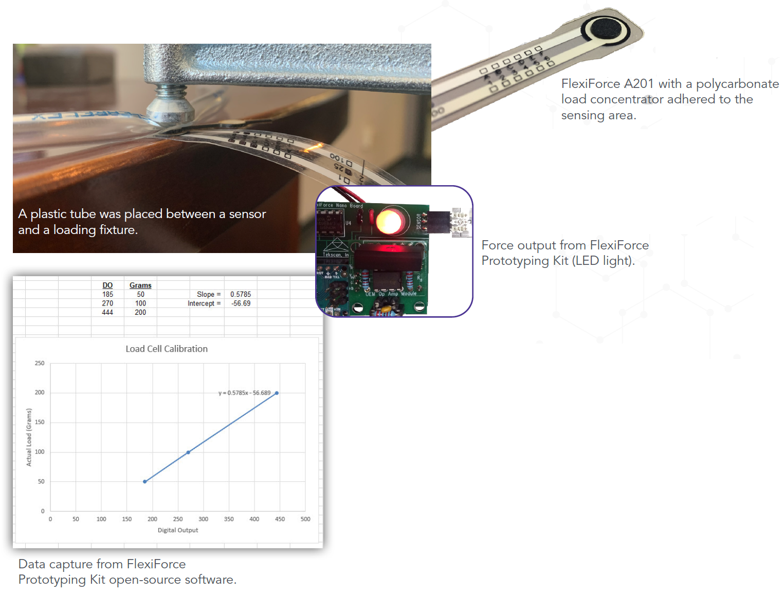
Figure 3. Proof-of-concept schematic. Image Credit: Tekscan, Inc.
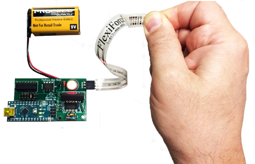
Figure 4. The FlexiForce Prototyping Kit. Image Credit: Tekscan, Inc.
Phase 3: Prototyping
The Prototyping phase is the initial build of a product or device with the sensor embedded once it has been established that the sensor will function under the parameters and loading profiles tested in the Proof-of-Concept.
This can become an iterative process where numerous prototypes are tested – often referred to as alpha- and beta-prototypes – that enable the engineer to analyze a device’s performance at different build sophistications.
Throughout this phase, engineers and designers have the following questions to answer:
- What calibration of the sensor is needed for my application?
- How am I going to accommodate for sensor-to-sensor variation?
- Can I reliably capture the desired measurement with the FlexiForce sensor embedded in a working device prototype?

Image Credit: Tekscan, Inc.
The Alpha Prototype was made up of the infusion pump’s housing, the fluid delivery tube, the embedded sensor and the voltage divider analog circuit module utilized throughout the Characterization and Proof-of-Concept phases.
With the linearity of the circuit selected during the Sensor Characterization phase, and the modifications made in the Proof-of-Concept phase, the design team developed a simple two-point calibration procedure with the assistance of the FlexiForce Prototyping Kit.
The team went back to the FlexiForce Characterization Kit loading fixture to apply known loads to the sensor and the interface materials selected for calibration. From that point, the engineers could test performance by passing fluid through the tube and observing feedback in a separate board display.
The team was able to troubleshoot any unforeseen performance issues with their benchmark data as they had characterized the sensor and proved concept with the same circuitry and material configuration in previous phases.
Once the team was happy with the Alpha Prototype’s sensor performance, they assembled a Beta Prototype with the same housing and tube, as well as the other HMI components planned for the design (digital screen, dials, buttons, etc.).
This version of the prototype also included the first rendering of the printed circuit board (PCB) for the application. For the sensor interface circuit of the PCB, the team used the open-source circuit diagrams and layouts of the analog circuit modules to make sure the same type of circuit was included in their PCB.
They also integrated adjustable reference voltage via a digital-to-analog converter (DAC) to accommodate any sensor-to-sensor variation.
While completing the alpha prototype, the team observed that the sensor’s data output was not stable. The sensor output was not repeatable given the presumed constant, cycled load applied to the sensor.
The team returned and compared the data obtained in the alpha prototype to the repeatability data captured for the same sensor and same circuit in the loading fixture of the FlexiForce Characterization Kit.
By monitoring and evaluating the data captured during the repeatability test in characterization, the team was confident that the sensor would produce a repeatable output with their repeatable load. Subsequently, the team turned towards the construction of the tubing in the prototype to determine whether it was supplying consistent load to the sensor.
They established that the tubing was configured in such a way that it could move off the sensor slightly when in use, which was the probable cause of the erratic data that they were seeing.
The team adjusted the assembly that held the tubing in place so that it would remain in contact with the sensor, finalized the prototype and presented it to product management for final approval.
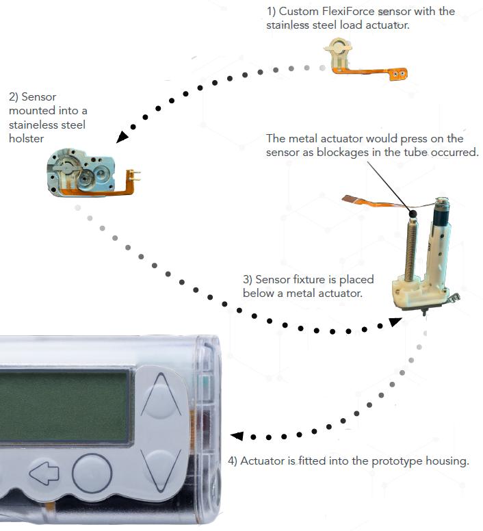
Figure 5. Prototype schematic for integrating the sensor. Image Credit: Tekscan, Inc.
Phase 4: Application & Field Testing
The Application & Field Testing phase necessitates fabricating multiple prototypes to test their performance, longevity and repeatability. The objective of this phase is to prove whether a design will carry out its required function in the field across the expected lifetime of the product.
For some particular products, including medical devices, this is often the phase where the product design is put forward for any third-party approvals. Throughout this phase, engineers and designers are looking to answer the following questions:
- Does field deployment call for additional design considerations not accounted for in previous phases?
- Does the selected material/electronics configuration operate as expected through the anticipated life of the product in the field?

Image Credit: Tekscan, Inc.
The design team designed ten infusion pump prototypes and sent them to ten different users for a six-week period. After the testing was completed, it was apparent that the force sensors in three out of the ten prototypes were not effectively detecting occlusion. Initially, they presumed that the sensor was at fault.
Upon subsequent review, the sensors met expectations when the prototypes were returned to the lab for testing. In reality, the design team established that the adhesive used for keeping the sensor in place on the pump was not performing well in humid conditions and was influencing sensor performance.
After an additional round of field testing with a new adhesive, the force sensor performed well across all prototypes. Had the design team not found the time to characterize and fully evaluate the sensor early in the process, it is possible that they would have overlooked this seemingly minor but crucial mechanical error.
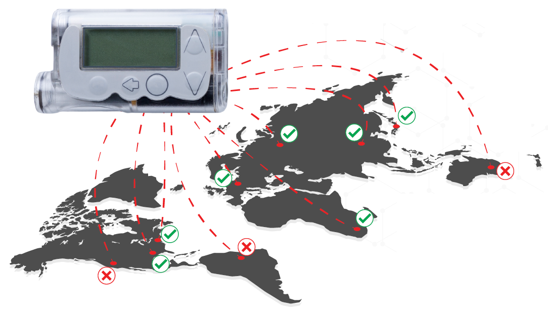
Image Credit: Tekscan, Inc.
Phases 5 and 6: Final Embedded Design and Transfer to Production
Phases 5 and 6 work in partnership with one another, with some slight differences. As its name suggests, the Final Embedded Design phase is the documentation of final design specifications that will be communicated for mass production.
These specifications are inclusive of calibration/recalibration routines, sensitivity adjustment and other variables. It is critical to think about how these design specifications can be carried out as efficiently as possible in mass production.
Finally, the Transfer to Production phase is the production process for the mass population of consumers or end-users.
In the majority of cases, this phase concludes the integration process, but there is always the possibility that design challenges may occur in this final phase that may necessitate a return to one of the earlier stages to rectify the issue.

Image Credit: Tekscan, Inc.
Since the infusion pump was a medical device, comprehensive documentation of each step of the manufacturing process was vital. The design team worked in close collaboration with the manufacturing department to answer for all of the critical nuances of the sensor integration process and to ensure these steps could be repeated for the mass population of users.
Image Credit: Tekscan, Inc.
Conclusion
Sometimes, the fastest way to market with an integrated device may at first seem slow, but the benefits are returned in several ways. As this design story described, the team made the decision not to take any shortcuts through the integration process, which proved invaluable when any unforeseen challenges arose.
Before proceeding into proof-of-concept and prototyping, the design team thoroughly tested the FlexiForce sensor technology with various circuitry, interface materials, adhesive methods and other possible variables.
Since the team had a baseline knowledge of sensor performance that was acquired early in the Characterization phase, they could answer for any sensor variations, whereas designers who skip this step may erroneously dismiss the technology as a poor fit.
To sum up, by using FlexiForce’s OEM Development Products, the design team were in the position to effectively answer the key, important questions from concept to market:
- What is the FlexiForce sensor’s fundamental performance?
- How does a FlexiForce sensor perform with the circuits and material interfaces we are considering for any given application?
- Can I successfully capture my measurement as desired with the FlexiForce sensor and the electrical/mechanical configuration I have chosen in a “one-off” test that is representative of the application?
- How am I going to calibrate the sensor for my application?
- How am I going to accommodate for sensor-to-sensor variation?
- Can I capture the desired measurement with the FlexiForce sensor embedded in a working device prototype reliably?
- Does deployment in the field call for design considerations that were not accounted for in prototyping?
- Does the selected material/electronics configuration operate as expected through the anticipated life of the product in the field?
How Tekscan can be of Help in the Integration Journey
FlexiForce Sensor Characterization Kit
Phases Served: Phase 1
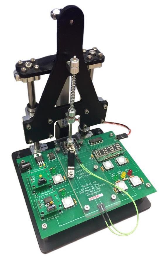
Image Credit: Tekscan, Inc.
The Characterization Kit allows engineers and designers to acquire a baseline understanding of FlexiForce sensor performance in a controlled loading environment prior to proof-of-concept or prototyping phases.
This saves the engineer time on constructing a testing fixture and building/debugging circuits.
The FlexiForce Sensor Characterization Kit includes:
- Desktop loading fixture with a load cell (available in 1 lb and 5 lb options)
- Three interchangeable circuit modules featuring Tekscan’s recommended circuits
- Voltage divider
- Inverting op-amp
- Non-inverting op-amp
- Pre-programmed loading profiles in an open-source software program
- Linearity
- Hysteresis
- Drift
- Repeatability
- (4) FlexiForce A301 sensors
- A301-1 (for 1 lb option)
- A301-25 (for 10 lb option)
FlexiForce Prototyping Kit
Phases Served: Phases 2, 3 and 4
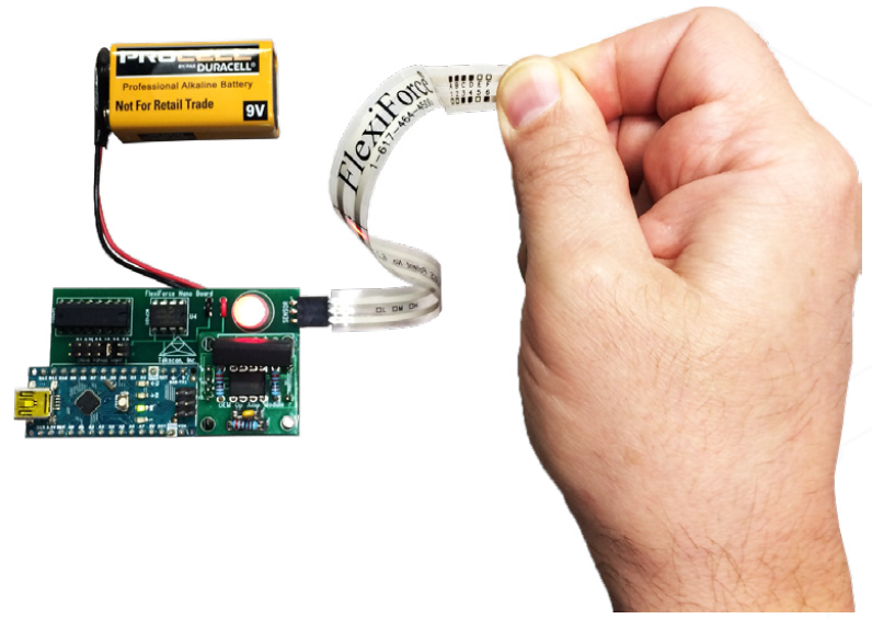
Image Credit: Tekscan, Inc.
After sensor characterization, the Prototyping Kit is a basic plug-and-play unit for engineers to test their desired circuit module(s), make sensitivity adjustments easily and have increased confidence in how the FlexiForce sensor will perform in their final design.
The open-source nature of this kit means that field-testing and final embedding are more effective and efficient.
The FlexiForce Prototyping Kit includes:
- An Arduino Nano Chip USB interface prototyping board
- Three interchangeable circuit modules featuring Tekscan’s recommended circuits
- Voltage divider
- Inverting op-amp
- Non-inverting op-amp
- Sensitivity adjustment
- Data collection/calibration software
- (4) FlexiForce A301 sensors
- A301-1 (for 1 lb option)
- A301-25 (for 10 lb option)
Put FlexiForce Sensors to Work
Now is the time to think about how incorporating force sensing technology into your products will give you a competitive edge. There are four questions that should be answered before establishing a process:
- What force sensing technology can effectively and economically be integrated into my product design?
- What mechanical or electrical requirements or obstacles may impact my choice of force sensing technology?
- Does my product require capturing force within a specific sensitivity range?
- Is my choice of force sensor backed with a support group of expert engineers experienced in embedding force sensing technology?
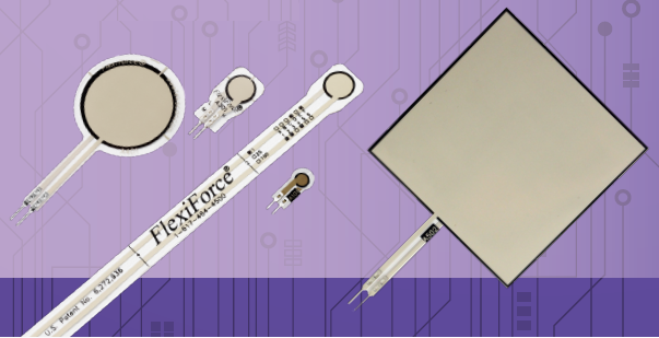
Image Credit: Tekscan, Inc.
Whether it’s a standard FlexiForce sensor or a custom design, Tekscan has a track record proven to help design engineers accomplish high-value products with force sensing technology. The user’s return on investment comes in the form of confidence in the product design, a reduced development process time and an enhanced end-user experience.

This information has been sourced, reviewed and adapted from materials provided by Tekscan, Inc.
For more information on this source, please visit Tekscan, Inc.