In order to perform temperature profiling in oil and gas, refining and petrochemical applications, the appropriate instruments can be easily sourced, but it is essential that care is taken during installation and use.
Establishing temperature ranges across a process unit — such as a furnace, desalter, hydrofiner, fixed-bed reactor or hydrocracker in refineries or similar process units in chemical plants — results in better process control, improved catalyst life, more efficient production, decreased emissions and fewer process upsets.
Known as temperature profiling, this technique grants access to temperature data from numerous sensors then sends the data to an automation system where control and monitoring software analyze the data and take appropriate action.
This article details the sensing devices used for the acquisition of temperature profile data. Although the sensing equipment seen in the examples is from Endress+Hauser, other instrumentation suppliers may offer similar equipment.
Profiling a Hydrofiner
A hydrofiner is a general application for temperature profiling. New environmental standards for low sulfur fuels are setting the terms for temperature profiling across the refining industry.
This new set of regulations calls upon plants to reduce air pollution emissions, specifically NOx, which results in the need to retrofit and upgrade existing equipment. For example, the sulfur content in mineral oil products has to be reduced, and this is usually achieved by catalytic desulfurization in a hydrofiner.
The oil is heated to 572-752 °F (300-400 °C) and raised to a pressure of 362-870 psi (2.5 to 6 MPa), then mixed with hydrogen to react with the catalyst.
The sulfur molecular connection undergoes a conversion process to H2S and hydrogen carbides. One of the problems with this process involves conducting temperature profile monitoring at the various catalyst layers of a hydrofiner (Figure 1).
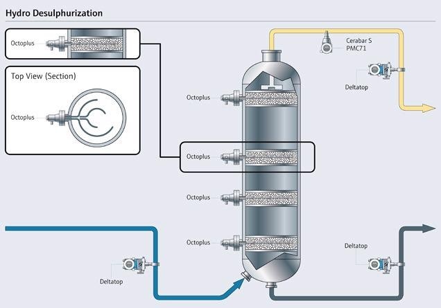
Figure 1. Temperature profiling at the different catalyst layers in a hydrofiner. Note the multiple sensors (top left ) inserted at each access point. Image Credit: Endress+Hauser Ltd.
A hydrofiner only has a limited number of access points are available, so a number of sensors have to be located at each access point across the layers
One way is to install a special “sensor array” with many sensors, all networked to a single transmitter. The Endress+Hauser Octoplus (seen in the top left corner of Figure 1) has numerous sensors necessary for the given application; individual thermocouples mounted in a single nozzle.
The unit’s “tentacles” can be placed within the reactor as necessary for monitoring the layer. Using data from numerous sensors, the control and monitoring software can generate a 3D image of the catalyst layer.
Temperature sensing elements can be switched out individually to minimize maintenance. The sensing elements are enclosed in a guiding tube that remains in the reactor. This means a faulty insert can be easily exchanged for a new one (Figure 2).
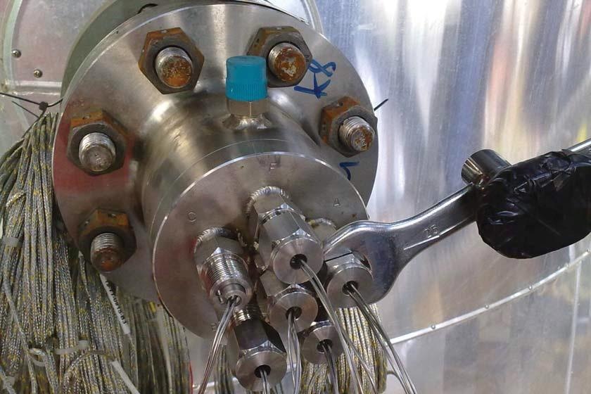
Figure 2. Individual temperature sensors can be quickly replaced. Image Credit: Endress+Hauser Ltd.
Temperature profiling with a sensor array is also practical for use in fixed-bed reactors. It may not be possible to attain a homogeneous reaction mixture as a result of the solid state of the catalyst. Formation of hot spots and cold spots may materialize, and coke formation can rapidly lead to the deactivation of the catalyst.
With numerous measuring points per process connection, sensors can be positioned freely in the reactor to determine problems. As a result, operations can be made aware of a degrading process situation quickly, allowing the necessary action to be taken.
Sensors are connected to a process transmitter or terminal block that can accept several sensors and then output 4-20 mA signals or thermocouple signals to the control system. Typically, either the terminal block or the transmitter is housed in an enclosure (Figure 3).
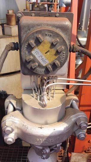
Figure 3. An enclosure contains either a terminal block that sends sensor data via the thermocouple cable to the control system or a transmitter that sends sensor data via 4-20 mA signals to the control system. Image Credit: Endress+Hauser Ltd.
Multipoint Thermometers
Another method for generating a temperature profile is with a multipoint thermometer, a temperature sensor with a long thermowell containing multiple sensors. The Endress+Hauser iTHERM TM911 (Figure 4), for instance, is comprised of multiple sensors, in an arrangement along the length of the thermowell.
The length of the thermowell can be in excess of 100 ft, allowing it to vertically extend through a reactor or process vessel.
While Figure 4 displays the sensor mounted across a reactor vessel, the sensor can also be vertically mounted or positioned at an angle as required to acquire different temperature profiles.
In theory, the maximum immersion length of each individual multipoint thermometer can be equivalent to the reactor’s internal diameter. To reinforce the end of the multipoint thermowell at the opposite side of the process connection, supports may be required.
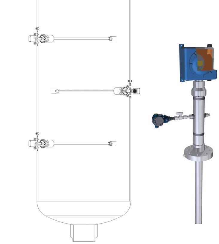
Figure 4. A multipoint sensor, such as the Endress+Hauser iTHERM TM911 (right), has multiple temperature sensors arranged along the length of its thermowell. The sensor can be placed so that it spans a reactor. Image Credit: Endress+Hauser Ltd.
Measuring Safely
In the oil and gas, refining and chemical industries, safety is always a primary focus. Therefore, extreme caution has to be taken when making multiple sensor connections because in nearly every case, the measurements are performed in a hazardous area, and/or the contents of the vessel are hazardous.
In the case of the sensor array, each of the process connections is a possible leak point as they leave the vessel. With numerous connections, this can present a problem.
Installing a safety chamber (Figure 5) between the flange and junction box for both the sensor array and multipoint thermometer is one solution. This stops process gases and liquids from escaping the vessel if a leak occurs in any of the process connections.
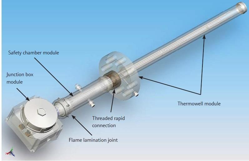
Figure 5. A safety chamber between the fl ange and junction box prevents process fl uid or gas from escaping from the vessel if a leak occurs. Image Credit: Endress+Hauser Ltd.
After long term usage under exacting process conditions, including high pressures, temperatures and corrosion rates — combined with a range of known and unpredictable process phenomena such as turbulence, highly exothermic local chemical reactions and others — a crack in the thermowell wall could occur, and the process media could seep in and fill the internal volume of the thermowell.
In this instance, the process media can be contained by second and third barriers (Figure 6).
By utilizing a pressure vent on the multipoint flange, the leak can be identified and monitored via a pressure transmitter. The second barrier means that the safety chamber is well-protected from any attack by highly corrosive process media, as well as from high pressures or temperatures throughout processes.
Even if the second safety barrier is breached, it is not necessary to shut down the entire plant as the safety chamber is in accordance with PED/ABSA pressure directives and their harmonized rules and calculation codes. This means that it can still operate safely until the next planned downtime.
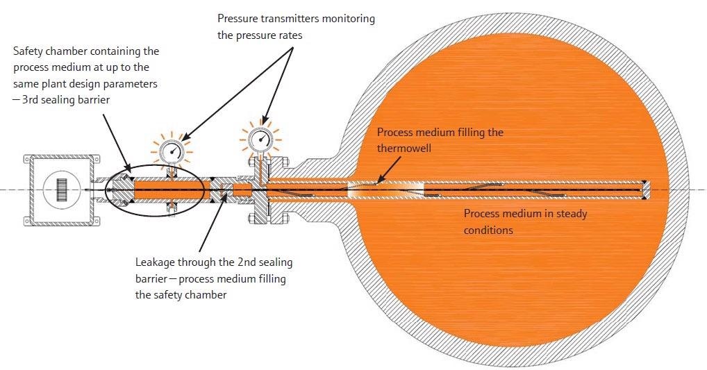
Figure 6. For extra safety, pressure transmitters can detect a leak. Image Credit: Endress+Hauser Ltd.
Summary
Modern flow technologies offer instrument engineers crucial self-monitoring information.
The format of such applications for temperature profiling in the oil and gas and petrochemical industries are determined by demanding process conditions in term of hazardous media with high pressures and temperatures — in combination with increased corrosion rates, turbulence and vibration.
Specialized instrumentation, such as array sensors and multipoint thermometers, are available to make the necessary measurements, but installation and use of the appropriate care and attention must be given.

This information has been sourced, reviewed and adapted from materials provided by Endress+Hauser Ltd.
For more information on this source, please visit Endress+Hauser Ltd.