Process manufacturing and other industrial facilities are required to present documented evidence of flowmeter performance on a regular basis to stay in compliance with numerous regulatory agencies, optimize production and ensure product quality.
Current smart instrumentation allows plants to achieve these tasks via built-in verification techniques traceable to known metrology standards. This article describes the ins and outs of self-verification.
Regulatory Requirements
In the water and wastewater industry, typical flowmeter requirements are:
- Flowmeters must be verified on a routine basis
- Verification must be performed by a qualified third party and with an accepted inspection method in accordance with quality regulations such as ISO 9001
- A test report must be provided for documented proof of verification
The water recovery industry generally utilizes large pipe sizes, and the recalibration of flowmeters used in these applications is extremely expensive. In several cases, a certified local reference standard, usually a mobile calibration rig accredited according to ISO 17025, cannot be accessed.
Moreover, in a number of instances, it is not acceptable to interrupt the supply or service of water, which makes it extremely difficult to extract the flowmeter from service for calibration (Figure 1).
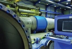
Figure 1. Removing a flowmeter for calibration and verification from a large line causes significant disruption and can be cost-prohibitive. Image Credit: Endress+Hauser Ltd.
These applications are ideal for self-verification as it limits the need to take flowmeters out of service. For drug manufacturers in the pharmaceutical industry, Quality Risk Management has become a compulsory regulatory requirement.
The Food and Drug Administration (FDA) and the European Medicines Agency (EMA) publish requirements and guidelines for process instrumentation that customers and vendors are required to follow.
Guidelines including “Process Validation: General Principles and Practices” by the FDA and Annex 15 issued by the EMA provide input to help drug manufacturers manage their instrumentation correctly.
The chemical industry has conditions for proof testing per IEC 61508 and IEC 61511, while the oil and gas industry must comply with contractual agreements between buyer and seller and adhere to any government agency mandates.
For instance, a company pulling oil from a well under an agreement with the Bureau of Land Management or the property owner may need to demonstrate that flowmeters are at a controlled frequency.
Calibration Vs. Verification
Contemporary flowmeters operating based on a Coriolis, vortex, electromagnetic, ultrasonic or thermal measuring principle contain no moving parts that would be subject to wear.
They may, however, have issues requiring recalibration due to the malfunction of an internal part or degradation as a result of temperature effects on electronics — or clogging, corrosion or coating buildups in the flowmeter body.
Legal requirements are usually satisfied with wet calibrations, where a flowmeter is extracted from the process (Figure 2), taken to a flow lab or calibration rig and evaluated using a formal comparison to a standard directly or indirectly related to national standards.
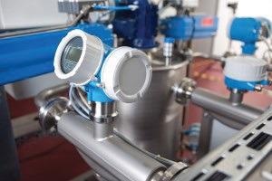
Figure 2. Flowmeters typically have to be removed from the process for calibration in a lab. On-board verification can determine when a flowmeter actually needs calibration. Image Credit: Endress+Hauser Ltd.
Changes that are detected between the reference value and the displayed value can be altered by adjusting the calibration factor after the calibration. A calibration protocol is published to document the findings. This is then put on record for potential future audits.
A drawback of wet calibration is that the instrument must typically be extracted from the process. The instrument is then returned to the facility for reinstallation after calibration. Damages during transport or handling may go undetected and cause a recently calibrated instrument to not perform per specifications.
Another way to meet legal requirements is with on-board verification of the flowmeter.
The flowmeter’s transmitter electronics contain an on-board diagnostics program, which inspects all relevant components of the instrument to document and confirm that the instrument remains within calibration and none of the meter components have wandered outside specific tolerances.
Verification of a flowmeter armed with built-in capabilities can be conducted without extracting the instrument from the process. It may not even be necessary to interrupt the process as the verification tests can all be carried out in the background.
A number of flowmeter manufacturers offer self-verification, and each works in different ways. This article uses Heartbeat Technology from Endress+Hauser as an example.
How Self-Verification Works
Modern-day flowmeters have been developed with integrated self-testing as a key part of the device from the offset. For instance, Heartbeat Technology was designed when Endress+Hauser’s new generation of Proline flowmeters was first developed.
This concept implants diagnostics in all flowmeter technologies that operate 24/7. Additionally, the entire signal chain from sensor to output can be tested using the flowmeter’s traceable, self-testing verification.
Verification in flowmeters fitted with Heartbeat Technology is predicated on continuous monitoring of all appropriate internal parameters, and mechanical, electromechanical and electronic components.
Generally, effects and diagnostic analysis in combination with a failure mode is in use during the flowmeter’s development phase to determine critical components in the signal chain, beginning with the process-wetted parts and followed by the electro-mechanical components, amplifier board, main electronic module and outputs.
An appropriate margin of safety is then allocated to each critical path or component. These tests include continuous loop checks and digital signal processing with the assistance of internal reference components.
When evaluating a Coriolis flowmeter — and additional time-based measuring principles like vortex or ultrasonic — a frequency reference oscillator is used to assess the frequency of the measuring tubes.
For electromagnetic flowmeters, this is a reference voltage because the measured value is established via a comparison of the voltage on the electrodes to the reference voltage. The primary reference is monitored using a second redundant reference system to ensure there are no changes during the lifecycle of the device.
The two reference signals from the primary and secondary references are contrasted against each other. A drift or deviation of the two systems from each other is detected immediately and declared by the device diagnostics.
An internal component employed as a diagnostic reference has to meet special requirements such as factory traceability and outstanding long-term stability. For the most crucial circuits, independent and redundant components are implemented, significantly reducing the possibility of unseen drift.
Today, it is possible to develop instruments with a self-diagnostics coverage of 94% or higher (in accordance with IEC 61508), and accordingly low rates of hazardous undetected failures.
Heartbeat Technology continuously monitors the entire signal chain for deviations within an extremely tight band. The failure threshold is marked by the specified accuracy of the flowmeter. If the diagnostics identify an error, Heartbeat Technology transmits an alarm message in compliance with NAMUR recommendation NE 107 (Figure 3).
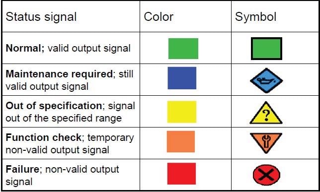
Figure 3. Diagnostic messages sent by Heartbeat Technology conform to NAMUR recommendation NE 107. Image Credit: Endress+Hauser Ltd.
The flowmeter’s front panel will display the alarm and this can be transmitted as a message over the interface to the automation system. The message also presents troubleshooting tips and remedial instructions.

This information has been sourced, reviewed and adapted from materials provided by Endress+Hauser Ltd.
For more information on this source, please visit Endress+Hauser Ltd.