In industrial process control, various methods exist for sensors and transmitters to convey measurement data. This article serves as an essential guide for understanding each type of signal and its typical application in measurement and control.
What are Analog Signals?
Analog signals denote continuous electrical signals representing the measured quantity. These analog signals can hinge on either voltage or current. The signal's scale adjusts according to the range of the measured variable.
To illustrate, think of an analog signal akin to a dimmer control for a light bulb, where altering the dimmer changes the light's intensity.
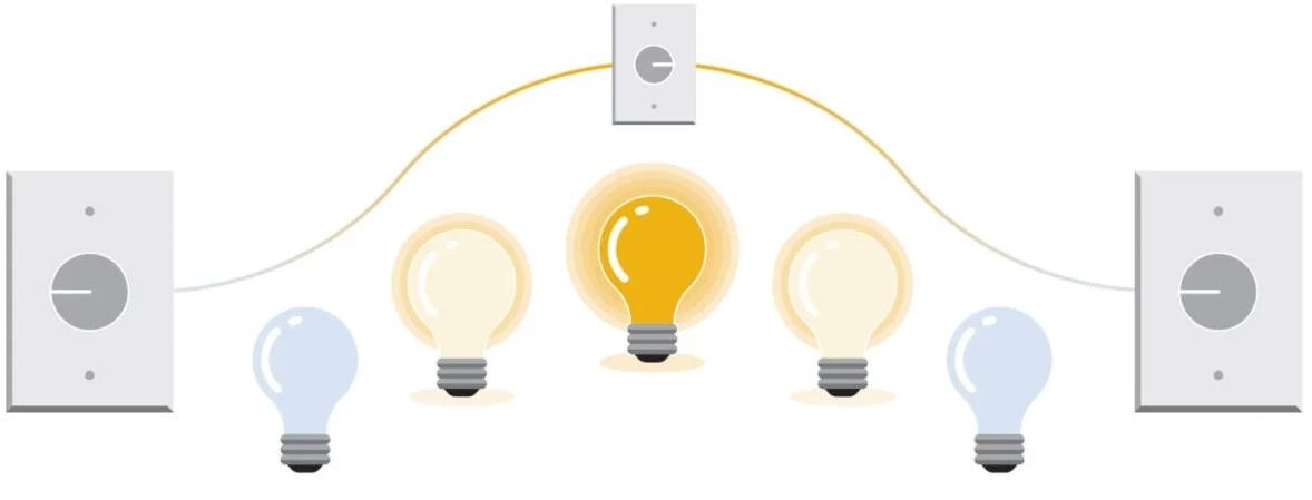
Image Credit: Hamilton Process Analytics
In the terminology of control systems, analog signals are often abbreviated as follows:
AI – Analog input
AO – Analog output
Common Analog Output Types
4-20 mA – The most prevalent analog output is the 4-20 mA current signal, widely applicable to measurements like temperature, pressure, pH, or conductivity. Typically, a 24-volt DC supply energizes this current output.
The transmitter translates the measured value into a 4-20 mA current output, with 4 mA representing 0% and 20 mA signifying 100%. There are multiple wiring schemes for transmitter connection:
- 2-wire (both current and voltage on the same +/- wires, often termed "loop powered")
- 3-wire (utilizing a shared 24 VDC power supply for both the transmitter/sensor and the 4-20 mA current signal)
- 4-wire (employing separate 24 VDC power supplies for the transmitter and the 4-20 mA current)
0-10 VDC (also 1-5 VDC) - Direct current (DC) voltage outputs are also common for process control, with 0-10 VDC frequently used in applications like building control (HVAC).
These voltages may cross over into industrial control. When uncertain, review the device's specifications to determine its voltage output range. Note that mA current signals can be converted to voltage by introducing parallel resistors into the circuit.
Millivolt - Sensors such as pH probes or thermocouples may produce a millivolt signal in correlation with the measurement.
For instance, a glass membrane pH sensor generates a signal ranging from +414 mV to -414 mV, corresponding to the 0 to 14 pH scale. Often, the millivolt signal is too feeble for long-distance transmission, so it gets converted into a 4-20 mA signal within the transmitter.
Nanoamp – Electrochemical sensors, like polarographic dissolved oxygen devices, generate a nanoamp current signal related to the density of oxygen molecules in the process. Similar to millivolt outputs, the nanoamp signal typically undergoes conversion to 4-20 mA within a transmitter to facilitate its use in existing control systems.
Advantages and Disadvantages of Analog Signals
The 4-20 mA signal, widely adopted since the 1950s, is universally accepted by most control systems. Its robust current is less affected by common sources of noise like EMI (electromagnetic interference) and RFI (Radio Frequency Interference).
When used in a 24 VDC loop-powered setup, a 4-20 mA signal may be allowed in a hazardous area, provided the electronics are designed and tested for low-voltage safety (intrinsic safety testing).
With the rise of digital communication, the limitations of 4-20 mA signals are becoming evident. This signal only represents the measurement's current proportion, so extra information such as diagnostics is unavailable.
What are Discrete Output Signals?
A discrete output is a straightforward on-off signal, often associated with a process's alarm point. For instance, if a pH measurement goes beyond the acceptable range, a discrete output can trigger an acid pump to adjust the pH.
During regular operation, the switch remains open, and the pump remains inactive. It only closes the switch to power the pump when the pH measurement gets too high.
In the lightbulb analogy, a discrete output functions like a traditional light switch, turning on and off as needed, with the required voltage coming from an external source.
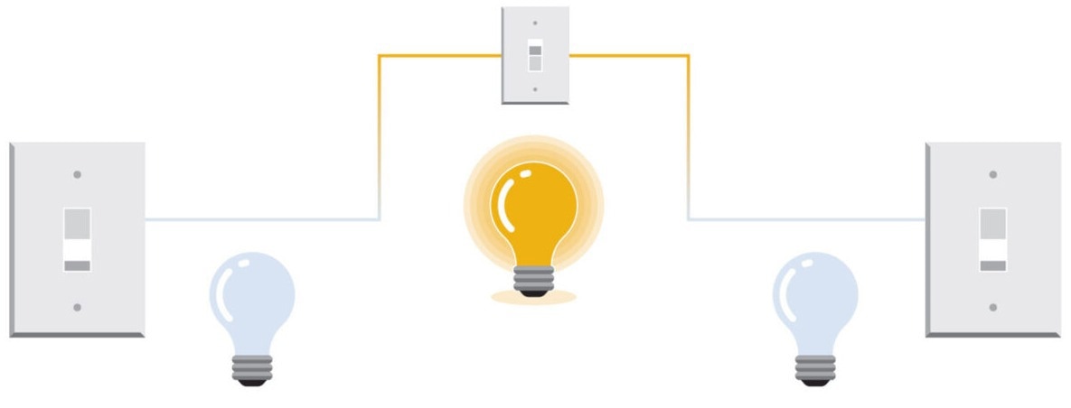
Image Credit: Hamilton Process Analytics
Discrete Signal Types
There are two common types of devices used for discrete signals.
- Mechanical Relays – This product operates much like the aforementioned light switch. It uses a metallic contact to complete the electrical circuit. An electromagnet typically actuates a mechanical relay to close the contact. Mechanical relays can generally handle higher amperage loads but may be slightly slower to actuate due to the physical nature of the connection.
- Solid State Outputs – These devices employ electrical components to complete the circuit. Unlike mechanical relays, they lack moving parts. Solid state outputs may use a transistor (DC) or triac (AC) for the switching mechanism. Solid state outputs are primarily used in low-amperage, high-cycle rate applications.
Moving to Digital Communication
While analog and discrete control signals remain the primary means of conveying process measurements, the trend is shifting toward digital communication.
Digital communication offers a way to transmit more comprehensive information about the measurement beyond the process variable itself. In the lightbulb analogy, consider what additional information could be valuable aside from the light's actual brightness.
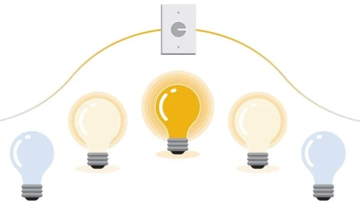
Image Credit: Hamilton Process Analytics
4-20 mA Analog Signal
Digital Signal
- Brightness of light
- Temperature of light
- Operating hours
- Number of on/off cycles
- Serial number of bulb
- Date of manufacturer
In the case of the lightbulb, this additional data can inform decisions about its condition. For example, reduced brightness may indicate dust on the lightbulb, requiring cleaning. Prolonged use or declining brightness may prompt preventive lightbulb replacement before it fails.
Another benefit of digital signals is the ability to take multiple measurements on the same connection, which can cut wiring costs and simplify design and installation.
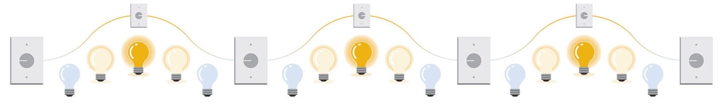
Image Credit: Hamilton Process Analytics
Types of Digital Communication
Different digital communication protocols have emerged as digital signals have advanced. Each protocol functions as its own unique "language," though the ultimate goal of transmitting measurement data remains consistent.
Modbus
The Modbus protocol traces its roots back to the introduction of the Programmable Logic Controller (PLC) by Modicon (now Schneider Electric) in the late 1970s. Modbus is classified as a serial protocol where data is sent and received on a single channel, one bit at a time, in a client-server format.
Two wires handle data transmission, while an additional pair of wires supplies power to the transmitter or sensor. Modbus relies on registers, which are variables that can be both read and written and must be configured on each device for effective communication.
Although Modbus is an older protocol, its open-source status is a major advantage, as it can be used by any developer without requiring royalties or licensing fees (for more information, see Modbus.org).
With time, the protocol has evolved to enable its use over TCP/IP (Ethernet) connections, offering added functionality for polling by multiple clients.
Hamilton Arc sensors utilize Modbus for digital communication, with each product having a Programmer's Manual providing register information for communication with the control system.
HART
HART stands for Highway Addressable Remote Transducer and was developed by Emerson in the mid-1980s. The HART protocol facilitates digital communication over the same 2-wire, 24 VDC loop power that many field transmitters have traditionally used for 4-20 mA signals.
The digital signal is a superimposed frequency that does not interfere with the current signal. This design has led to widespread adoption among users of traditional analog-based control systems. Over time, HART has become the most commonly used digital protocol for process measurement applications.
HART necessitates a Device Description (DD) file for each device, which is uploaded to the control system to fully recognize all variables present in the device. The protocol maintains a fixed 1200 bits/second (baud) rate, making it best suited for configuration or calibration but possibly too slow for rapid process control applications.
Hamilton offers HART support on its VisiFerm mA and VisiTrace mA optical dissolved oxygen sensors.
Profibus / Profinet
Profibus, a digital protocol developed by a government-backed German consortium in 1989, gained prominence when Siemens adopted it shortly after its launch. It became closely associated with Siemens' PLC products and garnered a devoted following in Europe. The Profibus digital protocol has evolved through various versions:
- Profibus DP – This protocol adheres to the RS 485 standard (also used for Modbus), separating power and signal wiring into two pairs. "DP" stands for Distributed Peripherals. Instead of running individual cables back to the PLC in the control room, all transmitter connections are managed at Input-Output (IO) termination points, which use a single serial link back to the controller. Profibus DP is known for its high-speed data transmission rates, reaching up to 12 Mbits/second.
- Profibus PA – Profibus PA is designed for "Process Automation" applications, with the communication signal residing on the 2-wire, 24VDC loop wiring used for field device power. Its design is similar to the HART protocol but without the 4-20mA signal. Profibus PA supports intrinsic safety requirements, making it suitable for hazardous area applications, with data transmission rates of 31.25 Kbits/second. Individual devices are connected to the control system through a segment coupler, providing power and converting PA to DP for high-speed data transmission.
- Profinet – Profinet transitions the protocol from RS 485 to Ethernet, enabling much higher data transmission rates, reaching 100 Mbits/second or higher. Unlike Profibus DP/PA's master-slave arrangement, Profinet offers greater flexibility, allowing multiple controllers to access device data in a duplex fashion, similar to most computer networks.
Profibus shares some similarities and advantages with HART. A GSD file is used to upload device variables into the controller. Profibus boasts much higher data transmission rates compared to HART (31.25 Kbits/second on PA vs. 1.2 Kbits/second with HART).
This added speed makes Profibus more suitable for actual process control applications. Hamilton provides several converters enabling Arc sensor Modbus signals to connect with Profibus DP and Profinet systems.
OPC UA
OPC is a standard for digital data transfer using Ethernet, originating in 1996 as an effort to standardize traditional "sensor protocols" like Modbus and Profibus into a computer-readable format. Early OPC versions, such as OPC DA, relied on Microsoft Windows.
These versions required extensive programming of sensor-specific data, known as creating a tag database. Variables like measurement range, decimal points, and units of measure had to be loaded into the OPC server for proper functionality.
The current standard, OPC UA, works across all platforms (Windows, Android, Apple, Linux) and automatically recognizes sensor-specific tag data, reducing the need for the painstaking programming associated with previous OPC versions.
Hamilton offers an Arc OPC Converter capable of powering and transmitting measurement signals from up to four Arc sensors.
Hamilton Connectivity
As a manufacturer, Hamilton recognizes the need to provide products covering a wide range of output signals. The infographic below summarizes the measurement parameters and the available control signals.
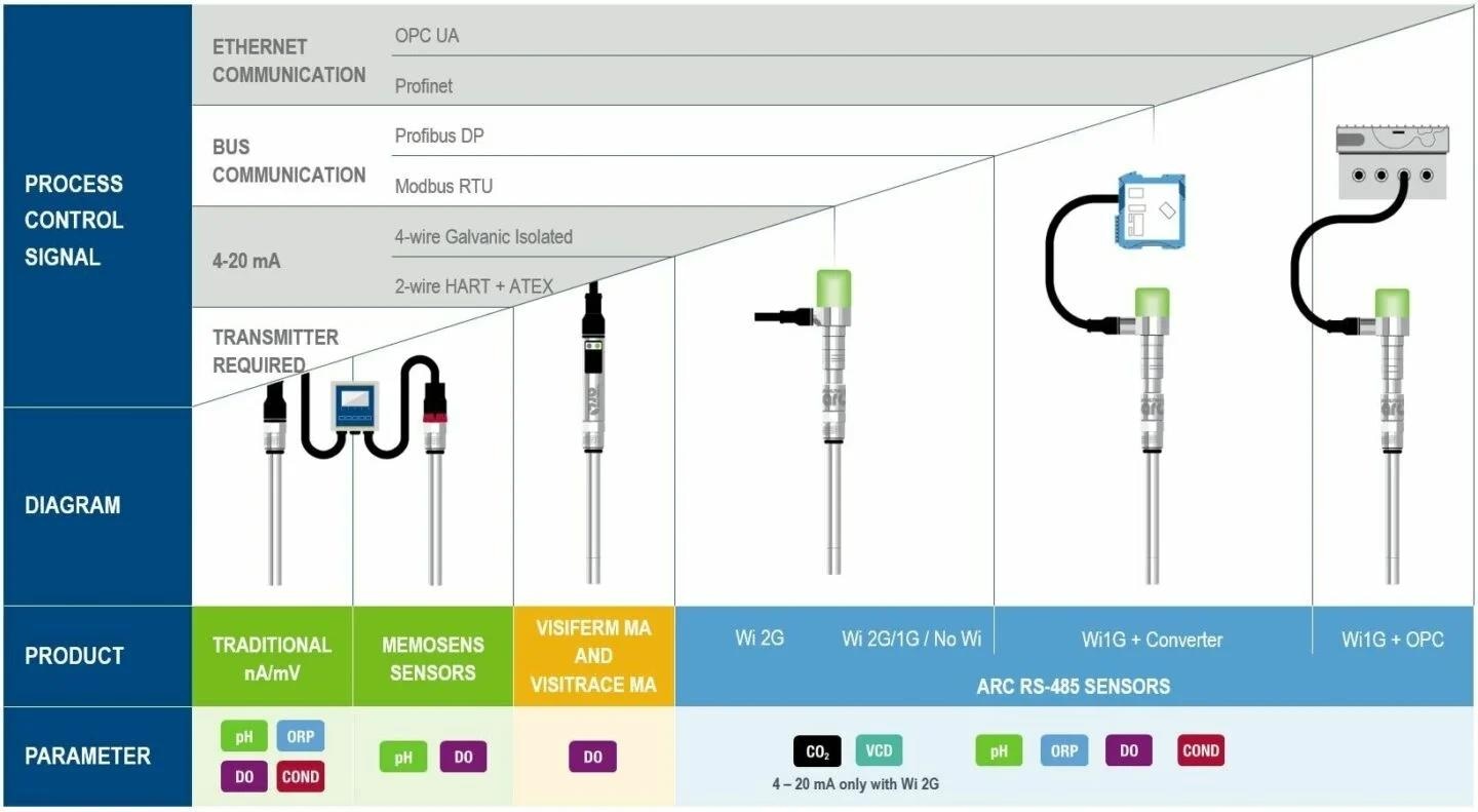
Image Credit: Hamilton Process Analytics

This information has been sourced, reviewed and adapted from materials provided by Hamilton Process Analytics.
For more information on this source, please visit Hamilton Process Analytics.