The thermocouple or RTD signal is converted to a 4 - 20 mA output signal using a temperature transmitter, which is considered to be the ideal solution for a number of remote temperature measurement applications. In comparison to conventional temperature measuring devices, temperature transmitters have definite advantages but must be selected with caution to avoid “ground loop” problems.
Why use Temperature Transmitters?
It is essential to monitor the temperature of a remote process in many cases. Extremely small signals are produced by common temperature sensing devices such as RTDs and thermocouples. It is possible to connect these sensors to a two-wire transmitter that will amplify and condition the small signal.
After being conditioned to a usable level, this signal can be transmitted through ordinary copper wire and used to drive other equipment such as controllers, computers, chart recorders, dataloggers or meters.
How to use a Temperature Transmitter?
Current is drawn using a temperature transmitter from a remote dc power supply in proportion to its sensor input. The actual signal is transmitted as a change in the power supply current.
Specifically, to measure the lowest temperature of a process, a thermocouple input transmitter will draw 4 mA of current from a dc power supply. With increasing temperature, the thermocouple transmitter will draw proportionally more current, until it reaches 20 mA.
This 20 mA signal corresponds to the highest sensed temperature of the thermocouple. The temperature range that the output current signal will represent is determined by the transmitter’s internal signal-conditioning circuitry (powered by a portion of the 4 - 20 mA current).
Physically, only two copper wires are needed to connect the temperature transmitter output signal in a series circuit with the process equipment and the remote power supply. This is made possible because the power supply line and the signal are combined (one circuit serves a dual function).
Choose the Right Temperature Transmitter
Compact M12 RTD Transmitters
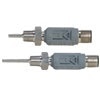
This unique probe is considered to be perfect for areas with space limitations, where traditional head connections are too large to fit. A secure industrial connection is provided by the M12 thread design.
Smart Temperature Transmitters
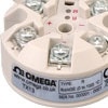
This smart head transmitter accepts thermocouple temperature sensors and transforms sensor output over a configured range to a standard industrial (4 to 20 mA) transmission signal.
Isolated 4 to 20 mA Transmitters
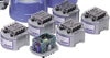
With no need for separate power input, two-wire operation power can be obtained directly from the 4 to 20 mA loop. This simplifies field wiring and prevents the possibility of noise pickup from power lines.
DIN Rail Temperature Transmitter
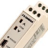
The TXDIN1600 Series has been custom designed to accept most common process and temperature sensor inputs. This new generation DIN rail mounted temperature transmitter provides the user with a standard two wire 4 to 20 mA output signal. Isolation is provided between output and input, and all temperature ranges are linear to temperature.
Advantages of Temperature Transmitters
Temperature transmitters provide many advantages over traditional temperature measuring methods:
- AC power is not required at the remote location in order to operate a two-wire transmitter
The supply of additional power at the remote location is not needed, as transmitters are powered by a low level 4 - 20 mA output current signal. Additionally, the usual 24 Vdc signal necessary for operation is standard in plants that have increased amounts of instrumentation.
- Electrical noise and signal degradation are not a problem for two-wire transmitter users
When it comes to ambient electrical noise, the transmitter's current output signal lends itself to a high immunity. Any noise that does appear in the output current is usually prevented by the common-mode rejection of the receiving device. In addition, the current output signal will not diminish (change) with distance as can be seen in most voltage signals.
- Wire costs decrease significantly when using transmitters
A shielded cable is almost always required by low voltage signals produced by thermocouples when they are sent any significant distance. Ambient electrical noise from ac power lines, motors and arcing electrical relays can raise havoc with these signals that are transmitted in an unshielded cable. Additionally, expensive, heavy gage wire is often installed in applications requiring long cable runs as it decreases errors from signal voltage drops caused by line resistance.
Ordinary copper wire can be used to connect all of the pertinent equipment in a two-wire transmitter system. The 4 - 20 mA current output signal is relatively immune to ambient electrical noise and does not get degraded by long distance transmission, even over a small diameter wire. The addition of a temperature transmitter to a system prevents the problem of having to provide long runs of costly wire and an increasing amount of shielding.
Ground Loop Problems
If a grounding rod was driven into the earth at two different points with a voltmeter connected between them, a voltage difference would be detected between them. This potential difference exists between practically any two points along the surface of the earth.
This voltage difference will induce an error current along the line, which is referred to as a “ground loop” signal, when an attempt is made to measure a process that is at a remote location. Its result will be an error at the display.
An isolating temperature transmitter should be selected for a system in order to prevent “ground loop” errors of this type. The sensor signal will be optoelectronically isolated from the output current loop by this type of transmitter. This will allow the user to ground both the sensor and one side of the current loop.
Features of the Temperature Transmitter
A two-wire output with the same wiring used for output and power is provided by transmitters. The load resistance is connected in series with a dc power supply, and the current drawn from the supply is a 4 - 20 mA or output signal which is proportional to the input signal.
Remote mounting of the transmitter near the sensor is allowed by two-wire transmission in order to minimize the effects of noise and signal degradation to which low level sensor outputs are susceptible.
Environmental protection and screw terminal input and output connections are offered by a rugged metal enclosure ideal for field mounting. This enclosure may be either surface or standard relay track mounted.
Even though new models are now available that are linearized to the actual temperature, most temperature transmitters are linearized to the voltage signal produced by the thermocouple or RTD.
The thermocouple or RTD signal is converted to a 4 - 20 mA output signal by the temperature transmitters. Some models will convert to an RS-232C output. Transmitters are available with dip switch selection for several thermocouple types per model, as well as thermocouple and RTD selection on a single model.
RTD and thermocouple transmitters are available in either non-isolating or isolating models, and they also feature output ranging adjustments with zero and span adjustments over 80 to 100% (based on model) of the sensor range.

This information has been sourced, reviewed and adapted from materials provided by OMEGA Engineering Ltd.
For more information on this source, please visit OMEGA Engineering Ltd.