Teledyne Judson Technologies provides a range of detector options for mid-wave infrared sensing. Indium antimonide (InSb) photodiodes provide excellent performance in the 1.0 to 5.5µm wavelength region. Single crystal p–n junction technology yields high-speed, low noise detectors with excellent uniformity, linearity, and stability.
Key Features
- Wide range of sensor sizes for all system needs
- Spectral range from 1.0 to 5.5 µm
- Can operate with either high-sensitivity or high-speed preamp
- Zero-bias operation compatible
Applications
- Heat-seeking guidance
- Thermal imaging
- Spectrometry
- Radiometers
- FTIR
When exposed to infrared radiation, photovoltaic InSb detectors produce current. The corresponding circuit for InSb is shown in Figure 1, which includes the shunt resistance (Rd), junction capacitance (Cd), and shot noise. The shot noise is caused by the background infrared radiation's DC background current (IBG). Smaller detectors have less shot noise and lower noise-equivalent power (NEP) values because IBG is proportional to the detector active area (Figure 3).
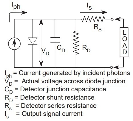
Figure 1. Image Credit: Teledyne Judson Technologies
Field of View: A standard cold field of view (FOV) is included at no additional cost. For a modest fee, a custom field of view can be provided. By limiting the FOV angle, detectivity can be enhanced, and IBG can be minimized.
The cold cutoff angle of the FOV should be selected to limit undesirable background radiation while receiving all desired radiation from the optical system. Unless otherwise specified, a 60° (full-angle) FOV with f/1 optics is provided.
Cold Filters: Optional cold filters can increase detectivity by reducing background radiation in undesirable wavelength areas. Figure 2 depicts the D* performance with the SP29 cold filter (0.5–2.9 µm) and the SP35 cold filter (1.7–3.5 µm ± 0.3 µm). Other bandpass filters can be ordered on a custom basis.
Dewar Packages: Operating temperatures of 77 °K are required for all J10D Series InSb detectors. The detector has a sapphire window and a 60° field of view in a conventional M204 or M205 metal dewar. There are more window and dewar choices available. All InSb detectors can be provided in the J508 or RC2 Detector Cooler Assembly for operation without bulk liquid nitrogen.
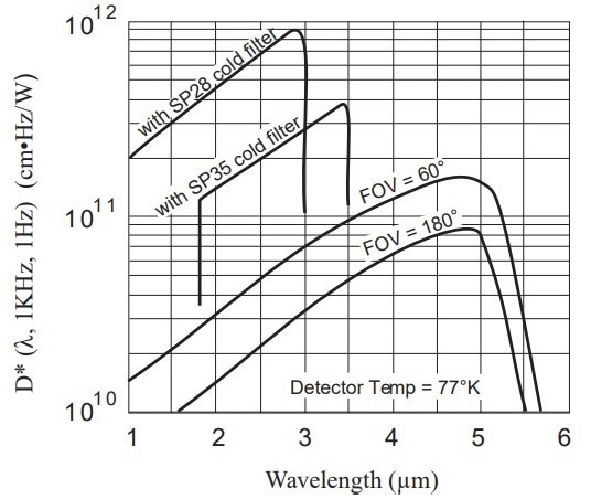
Figure 2. Image Credit: Teledyne Judson Technologies
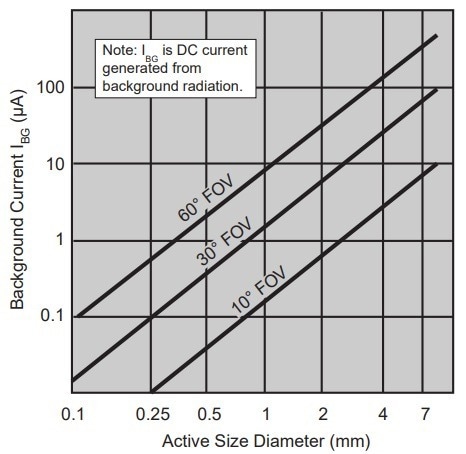
Figure 3. Image Credit: Teledyne Judson Technologies
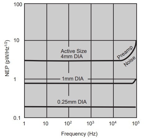
Figure 4. Image Credit: Teledyne Judson Technologies
Custom Detectors: Custom InSb detectors in any size up to 7 mm diameter and configuration are available. Judson offers specifications on linear position sensors, quad cells, and two-color (sandwich) detectors.
Preamplifiers: For best results, connect the InSb detector to a Judson trans-impedance gain preamplifier, which transforms detector output current to voltage while keeping the detector at the optimal zero-volt bias (Figure 5).
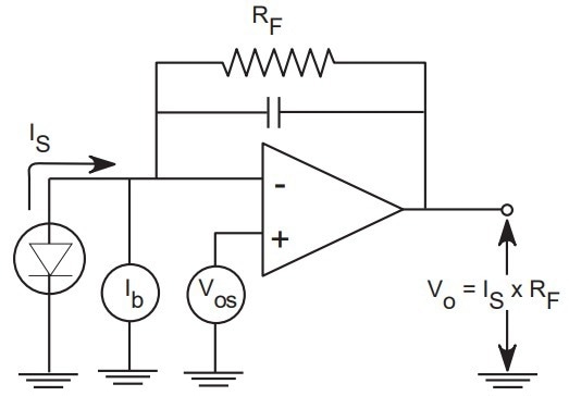
Figure 5. Image Credit: Teledyne Judson Technologies
The PA-9 preamplifier is tailored to each InSb detector for optimal sensitivity, gain, and bandwidth. Lower frequency applications suit the low-cost, adjustable gain PA-7 preamplifier (DC-10 KHz). Choosing the most significant practical value of RF while selecting preamp gain results in the lowest overall noise. To avoid DC saturation of the preamp, the detector IBG must be considered.
Example: The J10D-M204-R01M consists of a background current (IBG) of 7 µA (from Figure 3). Selecting RF= 1 MW will give a gain of 10E6 for a DC output of (7 µA x 10E6 V/A) or 7 V.
This is close to the saturation point of the PA-7 and PA-9. As a result, the highest usable DC gain for this detector is 10E6. For further amplification, an AC-coupled second stage can be added. Background current IBG can be minimized by using a cold filter or decreasing the field of view.
Source: Teledyne Judson Technologies
| Model Number |
Active Size(dia.) |
Judson P/N |
Peak Respon- sivity |
D* @ lpeak and 1 KHz |
NEP @ lpeak and 1 KHz |
Back- ground Current IBG |
Open Circuit Voltage VOC |
Shunt Resistance RD @ VR = 0V |
Capaci- tance CD |
Standard Packages |
| |
(mm) |
|
(A/W) |
(cm Hz1/2W-1) |
(pW/Hz1/2) |
(µA) |
(mV) |
(ohms) |
(nf) |
Dewar |
Window |
| J10D-M204-R100U-60 |
0.10 |
400151 |
3.0 |
1E11 |
0.08 |
0.15 |
90 to 120 |
>25M |
0.01 |
Side- Looking M204 M200 |
Sapphire Amtir 1-6µm AR Silicon |
| J10D-M204-R250U-60 |
0.25 |
400007-2 |
3.0 |
1E11 |
0.2 |
0.4 |
90 to 120 |
>10M |
0.03 |
| J10D-M204-R500U-60 |
0.50 |
400038-2 |
3.0 |
1E11 |
0.4 |
2 |
90 to 120 |
>1M |
0.1 |
| J10D-M204-R01M-60 |
1.00 |
400005-1 |
3.0 |
1E11 |
0.8 |
7 |
90 to 120 |
>500K |
0.4 |
| J10D-M204-R02M-60 |
2.00 |
400016-1 |
3.0 |
1E11 |
1.6 |
30 |
90 to 120 |
>150K |
1.6 |
Down- Looking M205 |
| J10D-M204-R04M-60 |
4.00 |
400010-1 |
3.0 |
1E11 |
3.0 |
110 |
90 to 120 |
>40K |
6 |
| J10D-M204-R07M-60 |
7.00 |
400057-1 |
3.0 |
1E11 |
6 |
350 |
90 to 120 |
>10K |
20 |