This article aims to design, develop, and test a small-scale rig, or a small-scale physical model, to verify the proposed mechanical hybrid system [1]. The small-scale rig was needed to reveal the transfer of energy between a vehicle and a high-speed flywheel at the time of the acceleration and regeneration periods. Additional tests utilizing this test bed can also be seen [2].
To save time and cost, the reuse of certain components salvaged from earlier experiments performed at Imperial College and then assembling them together in a single rig was believed to be prudent. Other students involved in these earlier experiments were assisted by the author, who was much familiar with what was available and what was suitable to reuse. At the time of developing the new experiments, the fabrication of extra components and the setup of the latest instruments for the rig were needed to achieve the required measurements. Figure 1 shows the overall design of the rig, which is characterized by having five important components:
- A high-speed flywheel serves as the energy reservoir
- A dynamometer to mimic the vehicle, and absorb and supply energy from and to the high-speed flywheel
- A double epicyclic gearbox transmission interlinks all the components
- A brake for decelerating the transmission ring
- An electric motor offers torque for the transmission and also energy to charge the high-speed flywheel
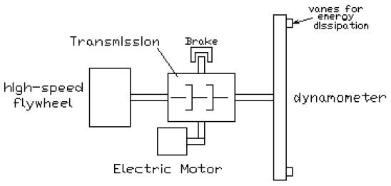
Figure 1. Overall design of the rig
The following sections present the system’s operational configuration and also include a description of all the parts.
Final Experimental Rig Set-Up
Complete Rig Configuration
The test rig’s configuration includes a brake, the flywheel, the transmission, the motor [3], and the dynamometer [7] — all set in a single assembly with the addition of instruments. A schematic outline of the experimental rig with a picture of the entire configuration is shown in Figure 2.
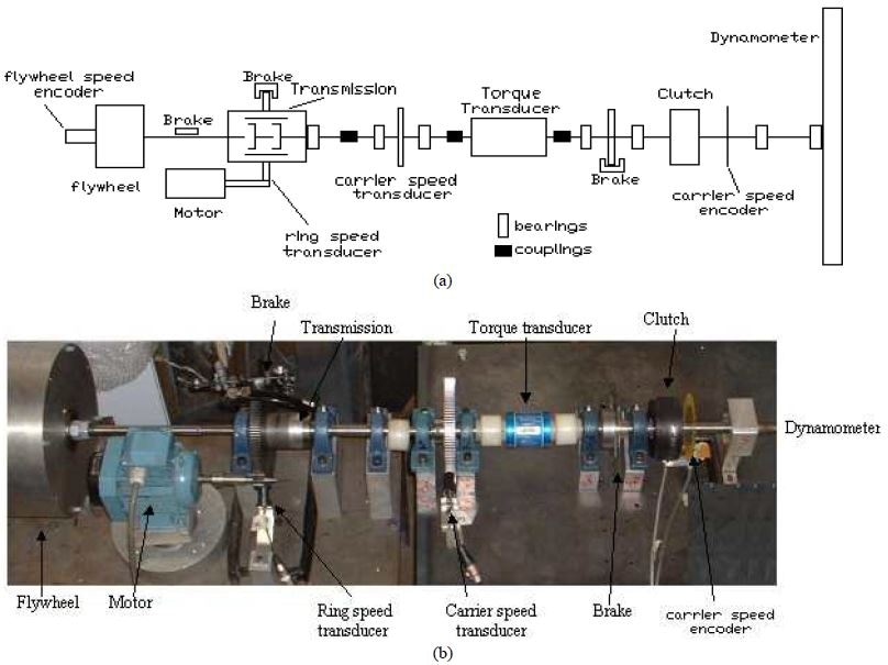
Figure 2. (a) Schematic diagram and (b) photograph of the complete rig showing the main components of the mechanical hybrid system and the instrumentation placed on the rig to experimentally investigate its performance.
The dynamometer and the epicyclic gearbox were mechanically interlinked through a pair of axially aligned soft couplings. To reduce the impact of bending, analogous kinds of couplings were fitted into the torque transducer. Instruments to determine the speed on the ring, dynamometer, and flywheel were installed on the rig. A clutch to separate the dynamometer from the brakes and carrier inhibiting rotation from the transmission branches were also used. Figure 2 shows the location of all the components integrated into the rig. The constituent components of the instrumentation layout fitted into the rig are described in the subsequent section.
Measurements
The below parameters were determined at the time of each test:
- Ring: rotational speed
- Flywheel: rotational speed
- Motor: electric power
- Dynamometer: rotational speed and torque
Measurement of Speed
The dynamometer and ring were installed with Hall effect pick-ups (see Figure 3) to feed frequency-voltage converters that operate within the speed ranges anticipated for each one.
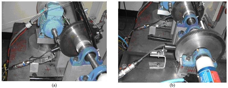
Figure 3. Photograph of the speed transducer for (a) ring and (b) dynamometer
As a result, the branches’ speed was relative to their output voltage. An electric motor was used to calibrate these transducers.
Besides the speed transducers, encoders were also installed on the dynamometer and flywheel shafts, as depicted in Figure 4.
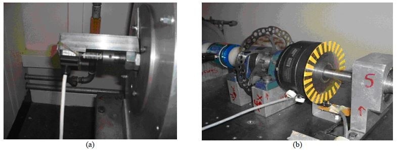
Figure 4. Photograph of the speed encoder for (a) flywheel and (b) dynamometer
These encoders provide several counts for every rotation of the shafts. In addition, the encoders installed on the flywheel shaft and the dynamometer shaft gave a count of 500 pulses and 25 pulses for each revolution, respectively. Subsequently, the speed was computed by associating the number of counts achieved over a time period.
At the time of the experimental measurements, it was observed that the electric noise coming from the motor inverter was responsible for corrupting the signal from the encoders; this invalidated the measurements from the encoders during the periods of motor operation. Conversely, the motor operation did not have an impact on the transducer’s signal; a double redundancy in the speed measurement helped in verifying that the speed of all the components was being measured accurately.
Measurement of Torque
A Sensors technology transducer model E300 RWT 1-1B was used to measure the torque. This technology is capable of measuring torque on rotary shafts utilizing surface acoustic wave, or SAW, technology. The torque transducer, shown in Figure 5 and already in place, was fitted on the dynamometer to give data on the torque being transmitted via this shaft. The inclusion of speed made it possible to calculate the power being transmitted through the dynamometer.
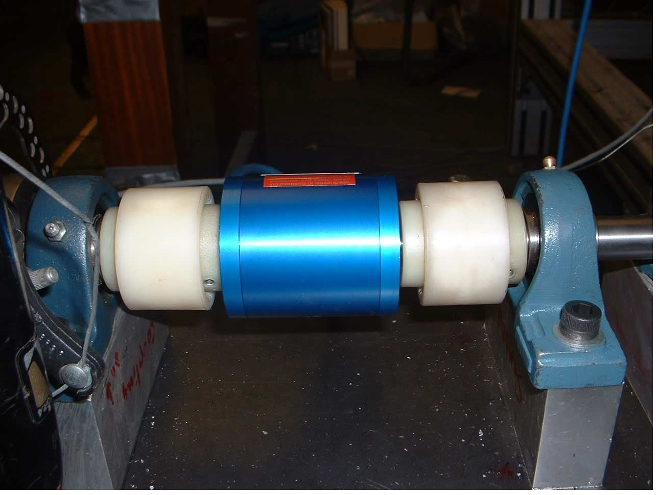
Figure 5. Photograph of torque transducer installed on shaft
Measurement of Power
A Voltech power analyzer, model PM3000A, was used to measure the electric input power. The analyzer can determine the on-line input power of the electric motor. It changed the power being used up by the motor to a 0–5 V analog output, thereby serving as a Wulff power transducer.
Data Acquisition System
A National Instruments card model DAQCard-6024E — with 12-bit multifunction I/O, 16 inputs, and 2 outputs — was used to obtain the experimental data. Grounded cables were subsequently fitted between the instruments and an interconnecting block. A virtual instrument (VI) was created in LABVIEW to offer a suitable interface between the digital and analog-digital data.
Experimental Tests
The main tests performed were:
- Run down test for the flywheel — the flywheel was speeded up with the motor up to a definite speed and then permitted to run down freely connected to the transmission.
- Run down test for the dynamometer — the dynamometer was speeded up with the motor up to a definite speed and subsequently permitted freely to run down connected to the transmission.
- Simple drive cycle — this test was particularly developed to verify the principle of operation of the mechanical hybrid power train. Once the flywheel was charged, the torque in the ring was regulated to operate the rig in flywheel assisted acceleration and regenerative braking.
Conclusions of the Measurements Conducted and the Experimental Test Bed
Therefore, it was validated that the experimental system was working in accordance with the theory. Measurements that were subsequently collected from the test bed agreed completely with the anticipated behavior. These outcomes were used to verify a computational model to evaluate the performance of such transmission in hybrid vehicles. The potential to reliably and dynamically design these types of systems using computational techniques in the ADVISOR/Matlab platform is evaluated and verified by comparing with these experimental tests [1].
The confirmation of the principle of operation of the mechanical energy storage system, as well as its computation model, was needed to confidently replicate the performance of real-size hybrid vehicles in the subsequent phase of this analysis. More explanation of this is provided in [1] and [2].
References
[1] Diego-Ayala, U. “An investigation into hybrid power trains for vehicles with regenerative braking”. PhD Thesis, Department of Mechanical Engineering, Imperial College, London, 2007.
[2] U. Diego-Ayala, P Martinez-Gonzalez, N McGlashan, and K R Pullen, “The Mechanical Hybrid Vehicle, an investigation of a vehicular regenerative energy capture system, ” Proceedings of the IMechE, Part D Journal of Automobile Engineering, vol. 222 (11), 2008, p. 2087-2101.
[3] G. Gretton, J. Noble, M. Gosling, and S. Thomas. The development of a hybrid transmission system for use in the shell mileage marathon vehicle. 3M DMT project report, Imperial College, London, 2002.
[4] Drivelines Technology. Power transmission solutions. Available at: http://www.drivelines.co.uk/.
[5] RS. AC Industrial Electric Motors. In Data Sheet 232-5812, vol. September, 2001.
[6] Allen-Bradley. User manual. In Bulletin 161 AC Drive (Series B) 0.2-3.7kW (0.3 to 5 hp) FRN 2.001.
[7] J. S. Wulff. Experimental validation of a novel hybrid vehicle transmission. MSc thesis in Department of Mechanical Engineering. London: Imperial College, 2004.
[8] Voltech. PM3000A Power Analyser User Manual. In manual VPN 98-051/5, 1998.
[9] T. Markel, A. Brooker, I. Hendricks, V. Johnson, K. Kelly, B. Kramer, M. O’Keefe, S. Sprik, and K. Wipke. ADVISOR: a systems analysis tool for advanced vehicle modeling. J. Power Sources, 2002, 110(2), 255-266.

This information has been sourced, reviewed and adapted from materials provided by Sensor Technology.
For more information on this source, please visit Sensor Technology.