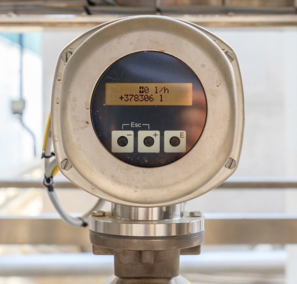
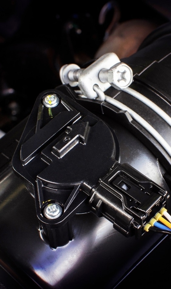
Mass air flow sensors are a kind of sensor utilized to analyze mass air flow; calculating the rate of gas traveling through a specified point at a determined time.1

There are a few slight differences between flow meters and mass air flow sensors for measuring rates of gas flow. Mass air flow measurements particularly record the number of molecules in a flowing gas rather than the flow meters that evaluate the volume.
Mass air flow sensors are commonly utilized in applications where it is critical to know precisely how much gas is present regardless of environmental conditions because gases are compressible and their volumetric flow rates are sensitive to changes in temperature and pressure.
Mass air flow sensors are frequently found in ventilation, automotive, and medical applications, and because of this, there are multiple frequently used designs of mass air flow sensors.
Hot-film or hot-wire sensors, cold-wire sensors, and other traditional designs such as Kármán vortex sensors, are all sensors that have subtly different approaches to recording mass air flow measurements.

 Download the Full eBook Here
Design Features
The majority of mass airflow sensors have multiple popular design concepts. The sensors can either be digital or analog, with the latter creating a variable voltage output and the former creating a frequency output.

As mentioned before, it is highly important to ensure that the sensor can analyze the mass of air entering the engine, rather than the volume, as this is what establishes the air-fuel ratio for the combustion process.
Regardless, directly measuring the mass of gas would be challenging, so instead, the volume of the air is analyzed, and the Ideal Gas Law (where the product of the volume and pressure is in proportion to the mass at a determined temperature), is utilized to translate this into a mass value.2
Direct Measurements
Hot-wire sensors are within this category of mass air flow sensors. These sensors are established on thermal loss concepts, where the incoming air travels over a heated, exposed element. An additional element is heated to an equal temperature.
By observing the current draw needed to keep the insulated element and the exposed wire at an equal temperature, mass air flow must be calculated.
This is due to the transfer of heat from the exposed wire being in proportion to the mass of air traveling over it. This technique cannot differentiate between backward or forward airflow so does not qualify as a true mass flow measurement.2
In the case of true mass flow measurements, which are critical in conditions where pulsating reversals of air flow are prevalent, a subtly different configuration of sensor must be utilized. Most of these sensors are established on porous silicon layers or micro mechanically fabricated free-standing membranes.3
By observing deformation of the membranes or residual stress, the air flow direction can be calculated and combined with the change in resistance as a result of the thermal changes of the gas flow; the true mass flow measurement can be determined.
Hot-film sensors act in a highly similar manner to hot wire sensors however the resistive element is a film instead of a wire. This helps to decrease the risk of breaking or snapping the wires, resulting in the sensors being more robust. The wire or film materials commonly employed have to be materials with high temperature coefficient of resistance, such as iridium, platinum, or rhodium.
Iridium and rhodium are frequently employed as alloys with platinum. It is now a possibility to miniaturize mass air flow sensors as micro-electro-mechanical systems (MEMS) sensors, where the whole device will conform to a small silicon chip. This is a popular sensor design for use in medical applications.
Housings
Along with the features of the sensor, the housing for a mass air flow sensor is a crucially important part of its design. If it is too restrictive, it performs as a choke mechanism for the air intake, which could possibly create limitations in the performance of the engine.
Therefore, the outlet and inlet sizes must be tailored to the estimated air intake range and to the application at hand. A large responsibility of the sensor housing is to act as a protective shield from outside contamination, because dirt on the sensors can result in sensor malfunctioning.
This is a frequent issue as sensors are commonly found in environments where pollution from oils or gases is a frequent risk.
Where backflow is a concern and for sensors that do not measure true mass air flow, the housing can be engineered to limit the influence of these effects. The design of flow channels in the housing can assist in managing the air turbulence and, consequently, reduces the amount of backflow.
The majority of mass air flow sensors include plastic housings or an inert material that will not be vulnerable to corrosion in the sensor environment. In some cases, aluminum or stainless steel is employed as an alternative. For performance car engines, the lightweight nature of aluminum is preferred.

 Download the Full eBook Here
References and Further Reading
- Mass Air Flow Sensors (2013), https://www.azosensors.com/article.aspx?ArticleID=156
- Fleming, W. J. (2008). New Automotive Sensors - A Review. IEEE Sensors Journal, 8(11), 1900–1921.
- Hourdakis, E., Sarafis, P., & Nassiopoulou, A. G. (2012). Novel air flow meter for an automobile engine using a Si sensor with porous Si thermal isolation. Sensors (Switzerland), 12(11), 14838–14850. https://doi.org/10.3390/s121114838
Disclaimer: The views expressed here are those of the author expressed in their private capacity and do not necessarily represent the views of AZoM.com Limited T/A AZoNetwork the owner and operator of this website. This disclaimer forms part of the Terms and conditions of use of this website.