Extrusion is a continuous process and successful economic production depends on maintaining stable melt quality and output and at a rate that is accurately controlled. The employment of DC drives, current screw design technology, raw material testing and computerized controllers help to deliver the melt to the extrusion die at quite a constant pressure, temperature, and viscosity.
Even the most minute change in the raw material or process will influence product dimensions. The manufacturing of small diameter tubing, which has to be held to ± 0.001" or less dimensional tolerances, is particularly sensitive to process instabilities. Differences in the raw material and process do happen in the production environment.
Monitors vary in speed, mechanical parts wear, ambient conditions change and temperatures fluctuate above and below setpoint. Some plastic materials are sensitive to storage temperature and moisture.
Each of these conditions can change and they all influence the stability of the product quality and extruder output (1). The key part that affects the quantity and quality of the melt produced by the machine is the extruder screw.
The most well-used extruder screw design has a transition zone, feed zone, and metering zone. Each of these zones within the extruder must carry out a certain function at the same time for stable output.
Table 1. Source: Dynisco
| Extrusion Zone |
Function |
| Feed Zone |
Solids Conveying |
| Transition Zone |
Melting/Pressurization |
| Metering Zone |
Pumping |
The flow rate through each of the three zones must be equal in order to attain stable output of the extrudate. Melting and pressurization happen at the same time in the extrusion, and inconsistency in either process will affect the other (2).
Random disturbance in both the mechanism of solid feeding and melting is due to raw material variation and inherent process. These lead to unstable conditions within the extruder.
With increased screw speed, instability in the extruder output usually increases in both severity and frequency (3). The output of the extruder is a function of drag flow and pressure flow:
Output = drag flow - pressure flow
Quantitatively expressed as:
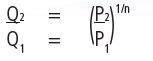
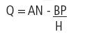 |
(1) |
Q = net volume rate of discharge
AN = vol. open discharge rate of melt
BP = volumetric back flow rate of melt
N = screen speed
P = pressure at head of extruder
A = screw constant based on screw geometry
B = screw constant based on screw geometry
π = apparent viscosity of melt in the metering section
As the screw speed increases, the pressure and output of the melt delivered to the die by the extruder increase also. Due to an increase in the pressure flow portion of extruder output, the pressure and output increase of the melt to the die is somewhat less than the increase in extruder screw speed, but this effect is typically small.
The output instability or surging of the extruder corresponds with the melt pressure at the die. Due to melt viscosity fluctuations, not direct interrelationship between output and melt pressure exists, but in practice, die pressure fluctuations correspond with output changes (4).
The flow rate through the die can be established by the amount of pressure at the entrance to the die. By definition, the die is a pressure-flow device. Die output is demonstrated in a similar form to the pressure-flow portion of the extruder output relationship:
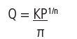
Q = flow rate from the die
P = pressure drop through the die
K = die constant based on die geometry
n = power law index of the melt
π = apparent viscosity of melt in the die
The screw exhibits the output and pressure relationship of the extruder and die and the die characteristic curves seen in Figure 1. The operating point for the system under the particular combination of conditions is represented by the intersection of the die characteristic curve and the screw characteristic curve.
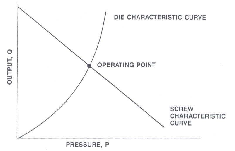
Figure 1. Output and Pressure Relationship of the Extruder Die. Image Credit: Dynisco
For a given screw geometry, a decrease in extruder output will shift the curve to the left and an increase will shift the screw characteristic curve to the right, as seen in Figure 2. By monitoring the pressure at the entrance to the die, alterations in extruder output can be identified.
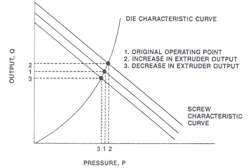
Figure 2. Effect of Changes in Extruder Output on Die Pressure. Image Credit: Dynisco
Changes in the extruder screw speed based on pressure at the die can be utilized to compensate for fluctuations in extruder output. Depending on the theological behavior of the polymer melt, a head pressure variation of 1% is roughly equivalent to an extruder output variation of 1-3% (5).
The die output expression, equation (2), shows this relationship between pressure variation and output. K, π and n are constant for a given die and melt system. The relationship between pressure fluctuation and change in output from the die can be expressed as:
Values of n for several plastics and a Newtonian fluid are given below:
Table 2. Source: Dynisco
| |
|
| LDPE/PP |
0.35 |
| HDPE |
0.50 |
| Nylon |
6 0.60 |
| FEP |
0.70 |
| Newtonian fluid |
1.00 |
Table 3. Pressure Variation. Source: Dynisco
| |
1% |
2% |
5% |
10% |
| Variation in Output |
| LPDE |
2.9% |
5.8% |
15% |
31% |
| PP |
2.9% |
5.8% |
15% |
31% |
| HDPE |
2.0% |
4.0% |
10% |
21% |
| Nylon 6 |
1.7% |
3.3% |
8.5% |
17% |
| FEP |
1.4% |
2.8% |
7.2% |
14% |
| Newtonian Fluid |
1.0% |
2.0% |
5.0% |
10% |
A variation in die pressure could result in three times as much variation in output from a material like LDPE/PP. It is worth noting that in actual practice, the output variations will differ due to a number of factors influencing the pressure and that these are theoretical values.
In all instances, the output variations of non-Newtonian plastics will be a multiple of the pressure variation at the die. So it is vital to know the pressure variation of the process even more so than the dimensional variation of the extrudate. Variations in pressure and, therefore, output are constantly occurring due to variations in the raw material and process.
The best technique to control both short term and long term pressure fluctuations caused by extruder surging is a closed loop feedback system that adjusts screw speed to maintain a constant die pressure. No downstream changes will be required if the extruder is slaved to the downstream equipment.
Test Technique
Test results can be seen in Table 3 and plotted on graphs shown in Figures 3 through 6, which show the effectiveness of closed loop feedback pressure control for minimizing output variations. Tests were performed on a 2½ " extruder processing 100% LDPE regrind at screw speeds of 35, 50, 70 and 100 rpm.
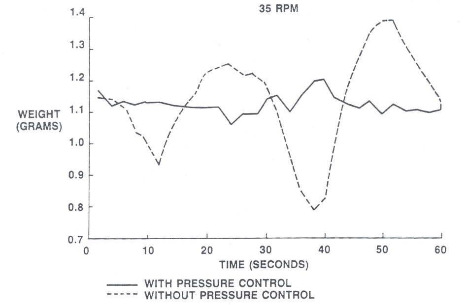
Figure 3. Image Credit: Dynisco
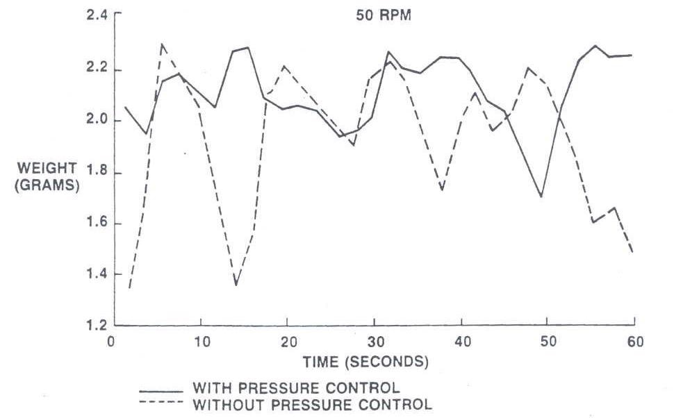
Figure 4. Image Credit: Dynisco
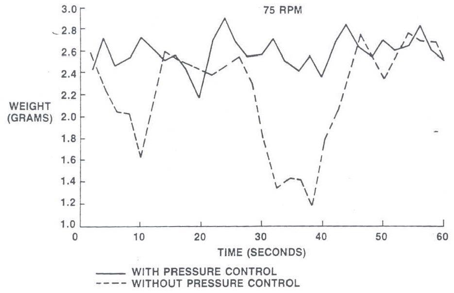
Figure 5. Image Credit: Dynisco
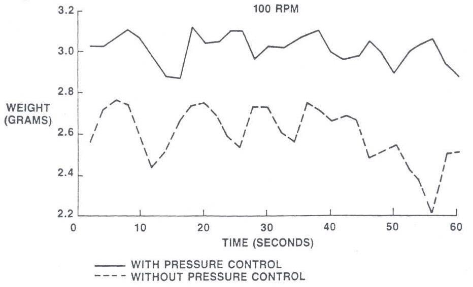
Figure 6. Image Credit: Dynisco
The utilization of 100% LDPE regrind simulates the worst surging conditions. The tests were made using a melt pressure transducer, which was mounted in the die and a microprocessor-based pressure controller.
The PID output of the controller was fed to the extruder drive. The output of the controller was utilized to adjust the screw speed continually to keep a constant die pressure.
- Graphs with solid lines indicate product linear weight over time with control of die pressure (continually adjusted screw speed).
- Graphs with broken lines indicate product linear weight over time with no pressure control (fixed screw speed).
Table 4. Test Results. Source: Dynisco
Extruder Speed
with and without
Pressure Control |
Polymer Pressure at Die |
Product Linear Weight |
|
| |
Avg |
Variation |
% Variation (B) |
Avg |
Variation |
% Variation (A) |
Change in
Product weight (A)
Change in
Pressure (B) |
35 RPM Nominal
w/o pressure control
w/ pressure control
% reduction |
1685
1870 |
85
90 |
11
4.8
56% |
1.075
14 |
0.325
0.0875 |
30
7.77
74% |
2.70
1.62 |
50 RPM Nominal
w/o pressure control
w/ pressure control
% reduction |
1625
1695 |
275
155 |
17
9.1
46.4% |
1.9
2.09 |
0.5
0.29 |
26.3
13.9
47% |
1.55
1.53 |
75 RPM Nominal
w/o pressure control
w/ pressure control
% reduction |
1775
2030 |
445
190 |
25.1
9.4
62.5% |
1.905
2.575 |
0.805
0.375 |
40.6
14.6
64% |
1.62
1.55 |
100 RPM Nominal
w/o pressure control
w/ pressure control
% reduction |
2650
2850 |
160
70 |
6.0
2.5
58% |
2.53
3.22 |
0.32
0.132 |
12.6
4.2
66.7% |
2.10
1.68 |
Results
The linear weight output variation was determined as 153% to 270% (1.53 to 2.70 times) of the pressure variation. The output variations were not as big as predicted theoretically in Table 3, based on the pressure variations that happened during the tests.
In every instance, linear weight output variation was higher than the pressure variation. The decrease in product linear weight output variation ranged from 47% to 74% (see Column A, Table 4). This suggests that, as a minimum, variations in output can be halved by utilizing closed loop pressure control.
Closed Loop Pressure Control for Melt Pump Extrusion
Melt pump assisted extrusion is growing in popularity as a technique for stabilizing the extrusion process. The literature states that a gear pump helps to stop drifting output rates and unexpected surges and from the extruder (2) (6-9).
Gear pumps are positive displacement devices that provide polymer melt to the extruder die at a relatively constant rate. The main function of the extruder in gear pump extrusion is to act as a plasticating unit to supply a homogeneous melt to the gear pump inlet.
The gear pump buffers the die from the extruder surges and drifts in output and is mounted between the extruder and the die. The inlet of the gear pump itself is subject to these extruder output variations.
A prolonged low-pressure condition could cause damage to the pump, as the pump needs a constant flow of plastic within certain pressure levels for lubrication. At the pump inlet, over pressurization due to a sudden surge of melt from the extruder will alter the melt condition and in extreme cases, it can be dangerous to the equipment and operator.
For these and other reasons, a closed loop pump inlet pressure control system, which alters the extruder screw speed to maintain a constant gear pump inlet pressure, provides various processing benefits.
A study which was undertaken by Dynisco and the University of Lowell found that a control system of this type improves and simplifies process operations by significantly reducing short term inlet pressure fluctuation, completely eliminating long term inlet pressure drift, decreasing the average inlet melt pressure, and increasing the safety of operation (2).
A brief summary of the results can be seen below:
Short Term Inlet Pressure Stability
Big changes in the inlet pressure indicate that to avoid dropping below minimum inlet pressure, a higher average inlet pressure should be utilized. Even a loss of inlet pressure that is temporary will show on the discharge side of the pump.
The energy input to the material is increased by the higher average pump inlet pressure, which increases the average melt temperature. Pump inlet and discharge pressures for both manual and closed loop operation at a pump inlet pressure setpoint of 350 psi are shown in Figure 7. Figure 8 indicates that short term inlet pressure variations were decreased by 70-80%.
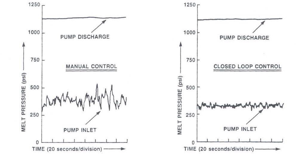
Figure 7. Short-Term Inlet Pressure Stability @ Pump Speed: 35 RPM (Approximately 105 RPM Extruder Screw Speed): Manual and Closed Loop Operation. Image Credit: Dynisco
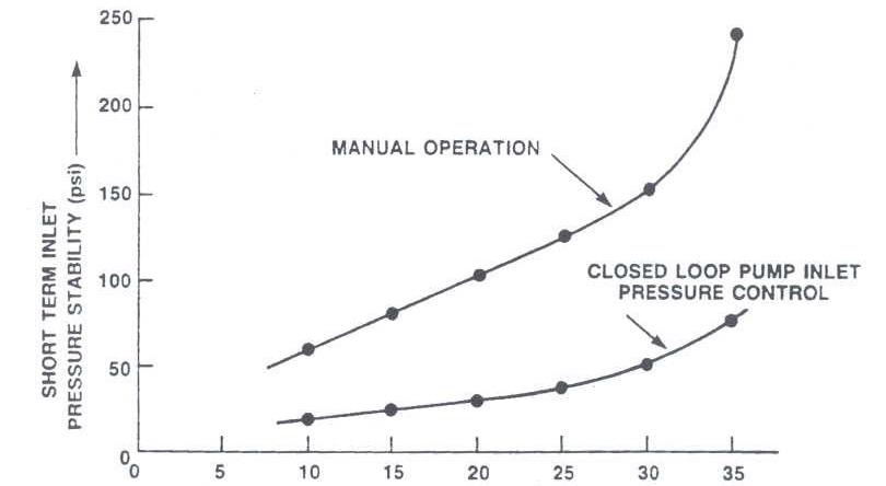
Figure 8. Short-Term Pump Inlet Pressure Stability vs. Pump Speed: Manual and Closed Loop Operation. Image Credit: Dynisco
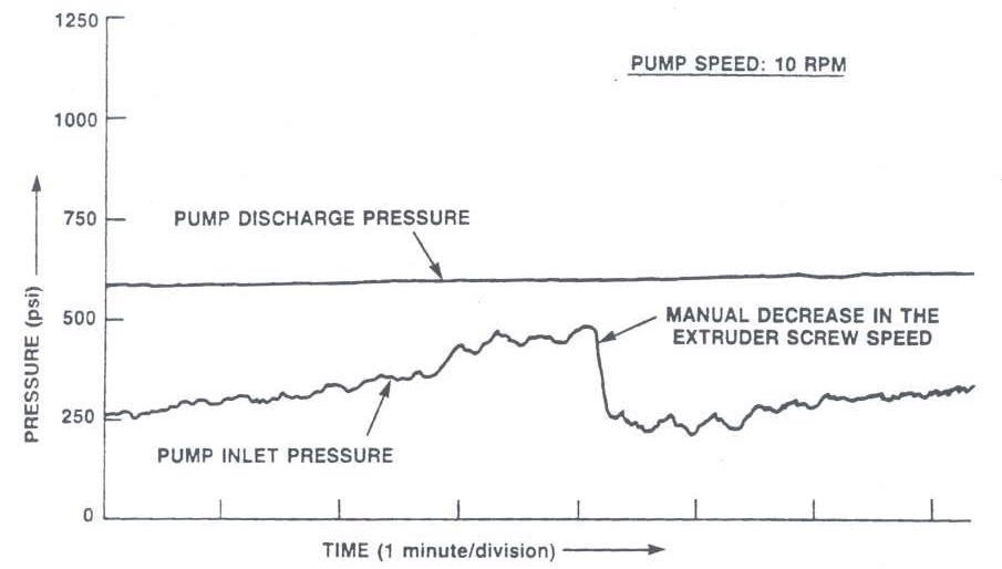
Figure 9. Long-Term Inlet Pressure Drift: Manual Adjustment in Extruder Screw Speed. Image Credit: Dynisco
Long Term Pressure Drift
It was necessary to periodically adjust screw speed when using manual control; this produced the result shown in Figure 9. Some short-term inlet pressure instability was observed with closed loop pressure control (Figure 10), but long-term pressure drift was eliminated completely.
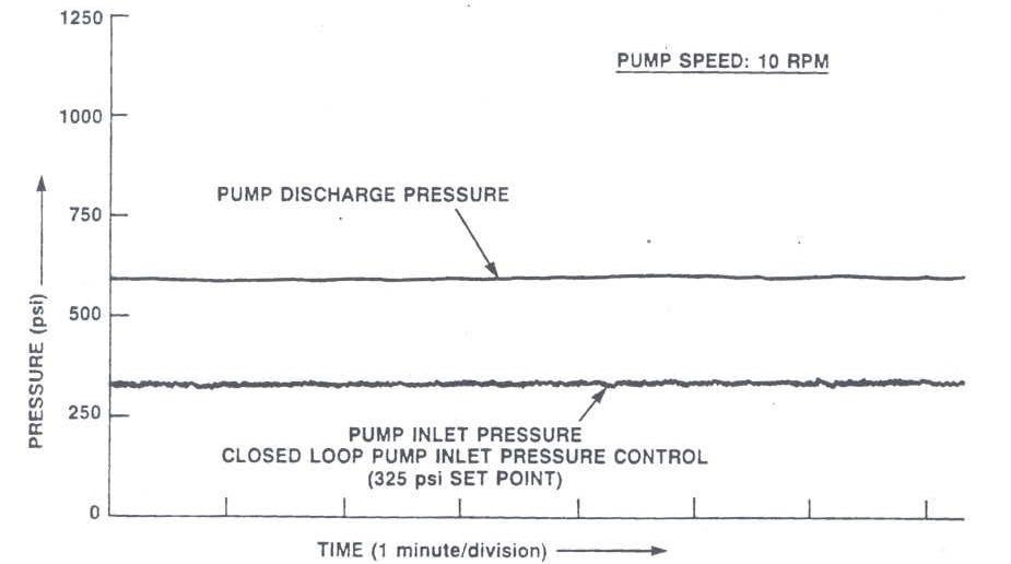
Figure 10. Long-Term Inlet Pressure Drift with Closed Loop Inlet Pressure Control. Image Credit: Dynisco
Process Output Change
With manual control, a well-coordinated, smooth change in output rate was hard to achieve. An increase in pump speed needed simultaneous and coordinated increases in extruder speed, often leading to excessive pressurization at the pump inlet.
The operation was considerably simplified with closed loop inlet pressure control. A decrease or increase in pump speed was automatically followed by the extruder (Figure 11).
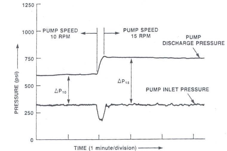
Figure 11. Closed Loop Pump Inlet Pressure Response to a Pump Speed Change. Image Credit: Dynisco
Safety
Operator and equipment safety is increased by closed loop inlet pressure control. If the pump ceases rotation and the extruder continues to pump polymer during manual operation, it only takes a matter of seconds for pressure at the pump inlet to reach dangerous levels. Electrical interlocks, mechanical rupture plugs, or high inlet pressure limits relays (a feature of some controllers) should be utilized.
Summary
Although modern extruder drives and take-off devices supply the user with a constant, drift-free operation, variations in the raw material and process happen, which causes the output of the extruder to alter. The output instability of the extruder is related to the melt pressure at the die.
The output variations of the extrudate will be a multiple of the pressure variation at the die. The most effective technique to minimize variations in extruder output is a closed loop feedback system, which adjusts screw speed to maintain a constant die pressure.
Inlet pressure instability is reduced by closed loop inlet pressure control for gear pump extrusion, as is the average minimum inlet pressure. Decreasing the inlet pressure variations assures a more uniform melt temperature at the die, thus improving the quality and consistency of the extrudate.
References
- Dynisco, Inc. "An Economical Method of Stabilizing the Extrusion Process".
- Malloy. Robert A., SPEC ANTEC, p. 604, (1984).
- Steven, M. J., "Extruder Principle and Operation", Elsevier Applied Science Publishers, pp. 101, 211, 237-248. (1985).
- I. Patterson, T. DeKerf, SPE ANTEC, p. 483, (1978).
- Frados, J. "Plastics Engineering Handbook, SPI, Fourth Edition", pp. 156-174, (1976).
- Fox, Steve A., Extrusion Technology for Tubing and Profiles Seminar, Killion Extruders, Inc. (1988).
- Kruder, George, PM&E, p. 24, Vol. 18, No. 5, (May 1989).
- Kramer, William A., SPE ANTEC, p. 23 (1985).
- Rice, William T., "The Case for Gear Pumps: What's Behind the New Interest", Plastics Technology, pp. 87-91, (February 1980).
- Maddock, B. H., "Measurements and Analysis of Extruder Stability", Union Carbide Technical Information.
- Plastics World "Extruders Gear Up for Tighter Gauge Limits", pp. 42-45, (July 1985).

This information has been sourced, reviewed and adapted from materials provided by Dynisco.
For more information on this source, please visit Dynisco.