The Transducer Must be Mounted Correctly
Damage to a pressure transducer is a result of improper installation into a poorly machined hole. When forcing a transducer into a hole that is too small or eccentric, the transducer diaphragm may be damaged and as a result, the instrument will not operate.
For machining the mounting hole, available tool kits will help ensure the holes are sized appropriately. A mounting torque of 100-to-200 inch pounds (for ½-20 UNF) is critical to forming a suitable seal; however, seizing will occur as a result of excessive mounting.
To avoid problems with seizing, prior to installation a high temperature anti-seize compound can be applied to the transducer threads. Removing transducers installed at a mounting torque above 500-inch pounds will be an arduous task even when applying an anti-seize compound.
Ensure that the Mounting Hole Thread Size is Correct
The abrasion from screwing a transducer into a mounting hole with an improper thread size will damage the instrument’s threads. This damage may inhibit a good tight seal, leading to material leakage and improper, unsafe functionality of the instrument.
The appropriate dimensions for the mounting hole must be used to prevent thread galling. The threads are typically the industry standard of ½ - 20 UNF 2B. A mounting well gage plug should be utilized to confirm that the mounting hole is machined and cleaned correctly.
The Mounting Holes Must be Clean
It is crucial to note that the transducer mounting holes are kept clean and free of any plastic build-up. Prior to cleaning, an extruder of the transducers should be removed from the barrel to avoid their being damaged.
When they are extracted, plastic is likely to pass into the mounting holes and harden. If this hard plastic residue is not removed, considerable damage to the tip will occur when the transducers are re-inserted.
Using a cleaning tool kit can help remove the contaminant plastic. However, excessive cleaning may produce ‘too deep’ holes and lead to damage to the transducer’s tip. If this is observed, spacers should be employed to raise the transducer.
Select a Good Location
Transducers may be positioned in the barrel, before and after a melt pump, before a screen changer, or in the die. When a transducer is placed too far upstream in the barrel, un-melted plastic pellets may corrode and damage the transducer tip.
If a transducer is placed too far back in the mounting hole, a build-up of a stagnant pool of melted plastic will occur between the transducer tip and the screw flights.
Over time this plastic will deteriorate to carbon, which will prevent the transmission of a precise pressure signal. Conversely, the screw flights can shear off the unit’s sensor tip if the transducer extends too far into the barrel.
Clean the Transducer with Care
Prior to cleaning an extruder barrel with either a wire brush or special cleaning compounds, removal of all of the transducers should be completed as either one of these can critically damage the transducer diaphragm.
The transducer should be taken out while the barrel is hot and using a non-abrasive cloth to wipe the tip clean. The transducer hole should be cleaned at this time with a cleaning drill/guide sleeve.
Avoid Cold Starts
Both the transducer and extruder can be damaged if the extruder is not at operating temperature before the machinery starts operations. An appropriate ‘soak time’ must be in place for the plastic to go from its solid to molten state.
Material might stick to the transducer tip if a transducer is extracted from a cold extruder, resulting in the diaphragm tearing off the unit. Ensure the barrel is warm enough prior to removing the transducer so that any plastic present will be soft.
Don’t Overpressure the Transducer
Transducers have been developed to withstand 1.5 times overpressure but avoid the risk of applying too much pressure by ensuring the use of the correct model. One designed for the range of extrusion operation pressures is being used.
Generally, use transducers that are manufactured withstand twice the rated pressure in any given process. Then the extruder will have to be functioning at an extreme, unsafe pressure levels for the transducer to fail.
Diaphragm Damaged by a Sharp Edge
Causes
- Contact with degraded polymer in hole
- Damage through sharp edge contact (screwdriver or knife)
- Dropped
Solutions
- Check hole with gauge plug for burrs or hardened plastic
- Clean hole with Dynisco cleaning tool
- Use protective cap (transport, storage)
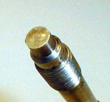
Image Credit: Dynisco
Diaphragm Ground off
Causes
- Contact with abrasive material in process
- Cleaning with wire brush or wheel
Solutions
- Dymax coating for abrasive applications
- Never use wire brush or cleaning wheel
- Wipe tip while hot with cloth to remove plastic
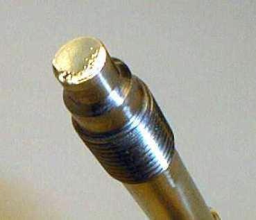
Image Credit: Dynisco
Diaphragm Torn
Causes
- Removal when the material was in a cold or hardened state - Shrinkage of adhesive materials
- Sensor located over flite (fatigue)
Solutions
- Double-strength Diaphragm (T80) or TiN coated diaphragm
- Remove while hot to avoid adhesion
- Relocate sensor
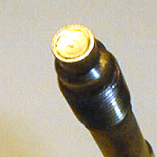
Image Credit: Dynisco
Diaphragm is Missing
Causes
- Diaphragm bonded to the material
- Removal in cold material condition
- Shrinkage of adhesive materials
Solutions
- Remove while hot to avoid adhesion
- Double-strength Diaphragm (T80) or TiN coated diaphragm
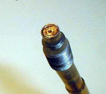
Image Credit: Dynisco
Diaphragm is Wavy; The Edge is Crushed on the Sensor Tip
Causes
- High shear tension
- Lateral crushing when installing (cross thread)
- Non-concentric mounting hole
Solutions
- Check the install location
- Check hole with gauge plug for burrs or hardened plastic
- Clean hole with Dynisco cleaning tool
- Double strength Diaphragm (option T80)
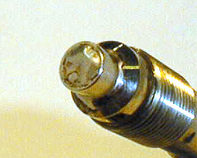
Image Credit: Dynisco
Shaft Bent
Causes
- External mechanical effect on stem
Solutions
- Stem is too long – shorten stem to match depth
- Over-torqued
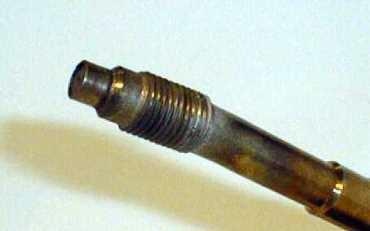
Image Credit: Dynisco
Shaft Torn off
Causes
- Mechanical effect
- Thread has been fused in the hole (galled)
Solutions
- Apply Anti-seize to thread prior to installation
- Follow torque requirements
- Use Hastalloy threads to minimize galling
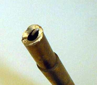
Image Credit: Dynisco
Seal Surface is Damaged
Causes
- Poor mounting hole or cross-threading
Solutions
- Check hole with gauge plug for burrs or hardened plastic
- Clean hole with Dynisco cleaning tool
- Verify threads with gage plug
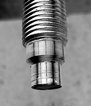
Image Credit: Dynisco
Flexible Connection (Capillary) Broken
Causes
- Bend radius too tight
- Capillary cut or stretched to capacity
- Installation damage
Solutions
- Handle carefully, due to exposed capillary
- Lengthen flex or use 435XL version
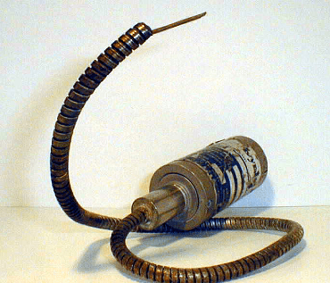
Image Credit: Dynisco
Thread Damaged
Causes
- Poor mounting hole
- Forced insertion/removal
Solutions
- Check hole with gauge plug for burrs or hardened plastic
- Clean hole with Dynisco cleaning tool
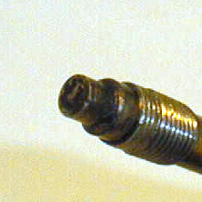
Image Credit: Dynisco

This information has been sourced, reviewed and adapted from materials provided by Dynisco.
For more information on this source, please visit Dynisco.