In addition to the wide range of two-dimensional (2D) nanomaterials that have already been documented in the literature, low-cost nanomaterials such as electrospun carbon nanofibers (CNFs) have also been used to construct flexible and wearable sensors.
Many procedures are used to make carbonaceous nanomaterials like CNTs and graphene; however, electrospinning is simpler and lower in cost. To accomplish somatosensory awareness in robots and next-generation prosthetic devices, building simple, dependable, and affordable skin-like artificial sensors linked with intelligent systems is critical.
Current problems associated with this problem can be solved by employing a two-pronged bioinspiration strategy. Here, skin-like wearable/skin-mountable sensors are used to imitate the skin, and a neuromorphic interface circuit is used to generate spike patterns, simulating neural firing and mimicking the human sense of touch.
Low-threshold mechanoreceptors (LTMRs) abound in the glabrous skin of the human hand, for example, and are made up of a mix of fast and slow-adapting LTMRs (RA/SA-LTMRs). Touch provides crucial information about the shape of the gripped object, its location, and the force produced by the fingers when robots accomplish fundamental tasks like object grabbing.
This necessitates both cutaneous tactile information, such as the force with which the hand presses the item, and haptic proprioception, such as the angle of the fingers or the position of the hand in relation to the arm.
To achieve real skin-like sensing, the system needs to include sensors that can sense pressure on fingers and joint tension, as well as electronics to convert sensor signals to brain impulses. A study published in ACS Applied Electronic Materials explores skin-inspired electrospun carbon nanofiber sensors for neuromorphic sensing to analyze human-machine interfaces.
To combine these two principles, CNF-PDMS-based piezoresistive sensors were combined with neuromorphic spiking neural networks in this study to produce skin-like sensing and proprioception sensors. To encode incoming signals and turn them into digital pulses (known as spikes) that maintain information in real-time, models inspired by biological neurons were used in this approach.
The behavior of a CNF-based piezoresistive sensing device is supplied to a simulated neuron in the first half of the study. The latter’s output is proven to encode information through spike count, which is comparable to a technique proposed for prosthetics applications in previous reports.
The strain sensor data are captured and connected with simulated neurons for imitating proprioception in the second (wrist conformation) and third (gesture recognition) sections. The simulated network could recognize certain motions by considering numerous CNF-PDMS strain sensors positioned at the finger joints.
A spiking neural network was produced by the interaction of these two layers of neurons and their connections. A future generation of smart gear with cutaneous and haptic abilities capable of replicating the somatosensory experience in prosthetics and robotic interfaces might benefit from a mix of networks with flexible, wearable, but simple and affordable sensors.
As illustrated in Figure 1(a), the skin is innervated by mechanosensory afferents, enhancing its somatosensory capacity. The mechanoreceptors that innervate the human skin are summarized in Figure 1(a).
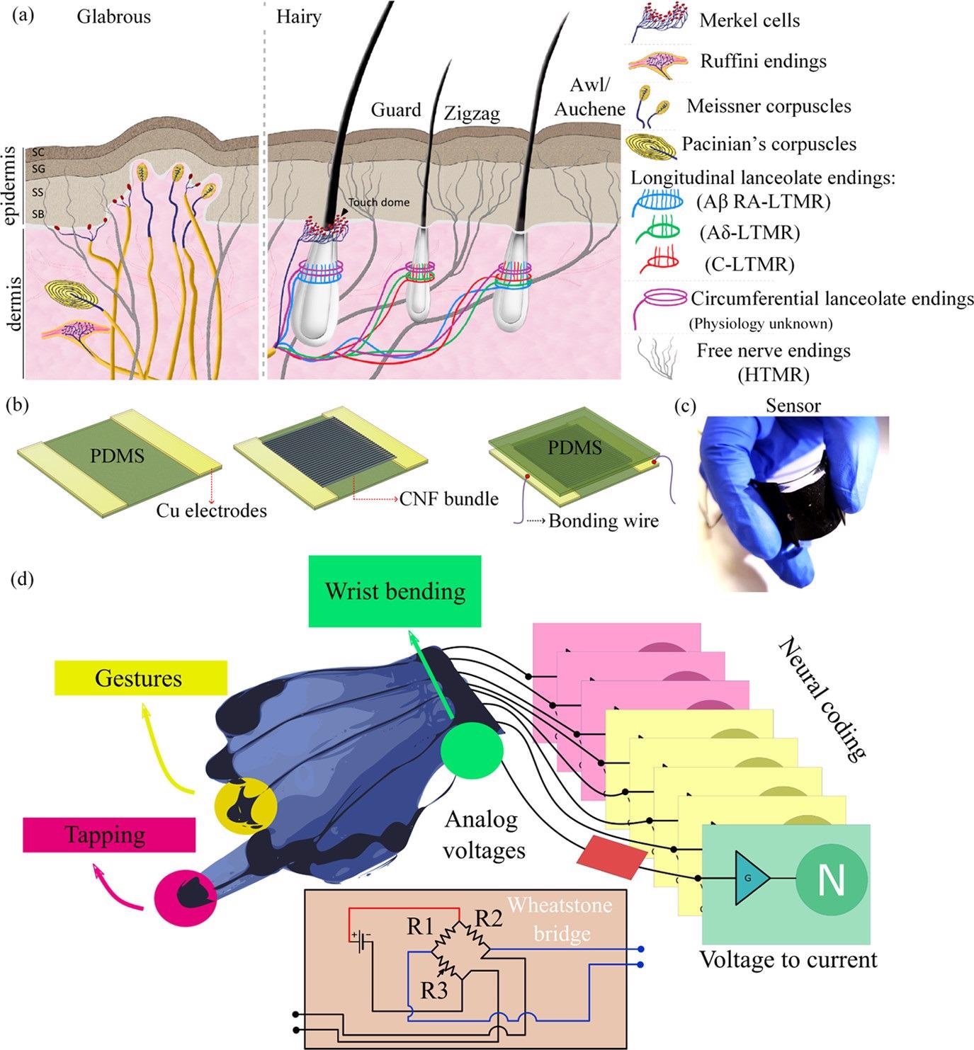
Figure 1. (a) Schematic representation of glabrous and hairy skins with their underlying mechanosensory receptors enabling their somatosensory ability. Reproduced with permission, (10) 2013, Cell press. (b) Schematic representation of the process steps involved in fabrication of the CNF-PDMS piezoresistive sensors. (c) Photograph of the fabricated CNF-PDMS tactile sensor. (d) Conceptual scheme of the final architecture. The glove will be equipped with tactile sensors on the palm and on the fingertips, with a wrist bending sensor and with stretch sensors able to detect gestures. The data will be then collected using Wheatstone bridges, converted to currents, and fed to a neural network which will use neural coding. Image Credit: Sengupta, et al., 2022
Results and Discussion
The implementation of the step that converts the pressure applied to a piezoresistive element to the current provided to a neuron is not investigated. Instead, the simulation in this paper was conducted with an ideal linear relationship between the pressure and the current output.
To demonstrate how adaptable and helpful a conversion to spikes may be, multiple forms of encoding are illustrated with distinct touch qualities in this study. The currents from the signals are supplied into a simulated artificial neuron with a leaky integrate-and-fire (LIF) architecture.
Discussion
Figure 2 shows how the sensor’s voltage (Vsensor) affects neuron behavior by plotting the voltage on the membrane (Vmem). Figure 2 also displays a neuron’s encoding ability, which embeds information about the sensor voltage’s amplitude into its spiking activity.
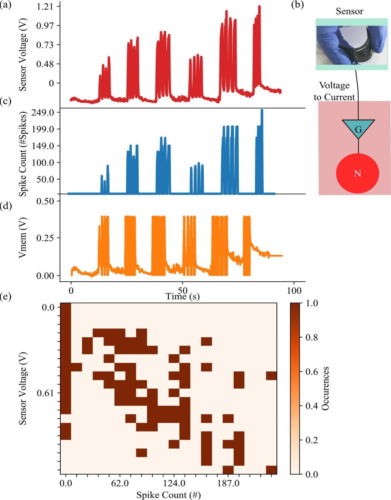
Figure 2. (a) Sensor voltage generated by different periodic pressures on the sensor. Different pressure values have been used to explore the response of the sensor with voltages up to 1.21 V. (b) Photo of the sensor along with the sensor readout schematic. (c) Number of spikes emitted by the connected neuron when the piezoresistor is stimulated. (d) The membrane voltage reaches 0.4 V, its value is rebased to 0 V, and a spike is generated. (e) Correspondence between the values of the sensor voltage (encoding the pressure) and the number of spikes emitted by the sensor. The number of spikes is calculated per 100 ms. Image Credit: Sengupta, et al., 2022
As seen in Figure 3(a), the number of spikes is closely related to the analog voltage created by the neuron. The statistical mean and standard deviation of voltage and spike trials are displayed in Figure 3(b).
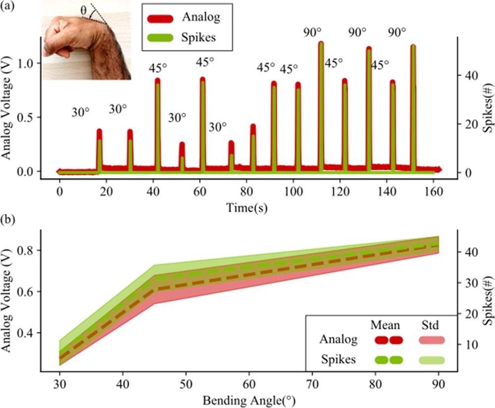
Figure 3. (a) Comparison between the response to wrist bending of both the sensor and the neuron. The sensor generates a voltage proportional to the bending of the wrist. This voltage is converted into a current and fed into a neuron, simulated on a computer. The number of spikes per 100 ms is here considered as spike count (or spikes #). Different trials for different angles are shown. The neuron follows the analog voltage with the number of spikes but does not generate any spike when the stimulus is only noise (this is visible in the lower part of the figure, where the spikes are 0 when no bending is performed). (b) Statistical analysis of the analog voltage and spike counts with different bending angles. The statistical deviation of the sensor is given by the human error in bending the wrist at a specific angle. This uncertainty is reflected quite well in the neuron with the spike count, which highlights the direct connection between a neuron spiking activity and a current coming from a piezo-resistive readout. This is to demonstrate the high degree of reproduction that the neuron has with respect to the analog values that it receives. Image Credit: Sengupta, et al., 2022
Figure 4(a) shows how the sequence of numbers (5, 4, 3, 2, and 1) causes time-varying responses in the five sensors. Figure 4(c) shows how the layer (i.e., a collection of neurons doing the same task) can properly translate the analog value of the bending into the number of spikes for every time step. Figure 4(d) depicts the whole network design, which is detailed in the Experimental Section. The network’s result for each gesture is seen in Figure 4(e).

Figure 4. (a) Response in voltage output of the five different sensors placed at the joint of the glove. The five sensors are plotted one over the other, from the little finger to the thumb. The five different colors superimposed to the graph highlight the different gestures performed in that moment. (b) Order of execution of five different gesture tasks performed with the glove. (c) Response in spike count of the five different neurons connected to the five sensors, plus the Poisson neuron, responsible for acting on the gesture “Five”. The five different colors superimposed to the graph highlight the different gestures performed in that moment. (d) Schematic describing the network used in this example. (e) Response of the decoding layer to the different gestures. Image Credit: Sengupta, et al., 2022
When the smart glove is utilized to conduct more sophisticated motions, Figure 5 depicts the connection between sensor output and spiking activity.
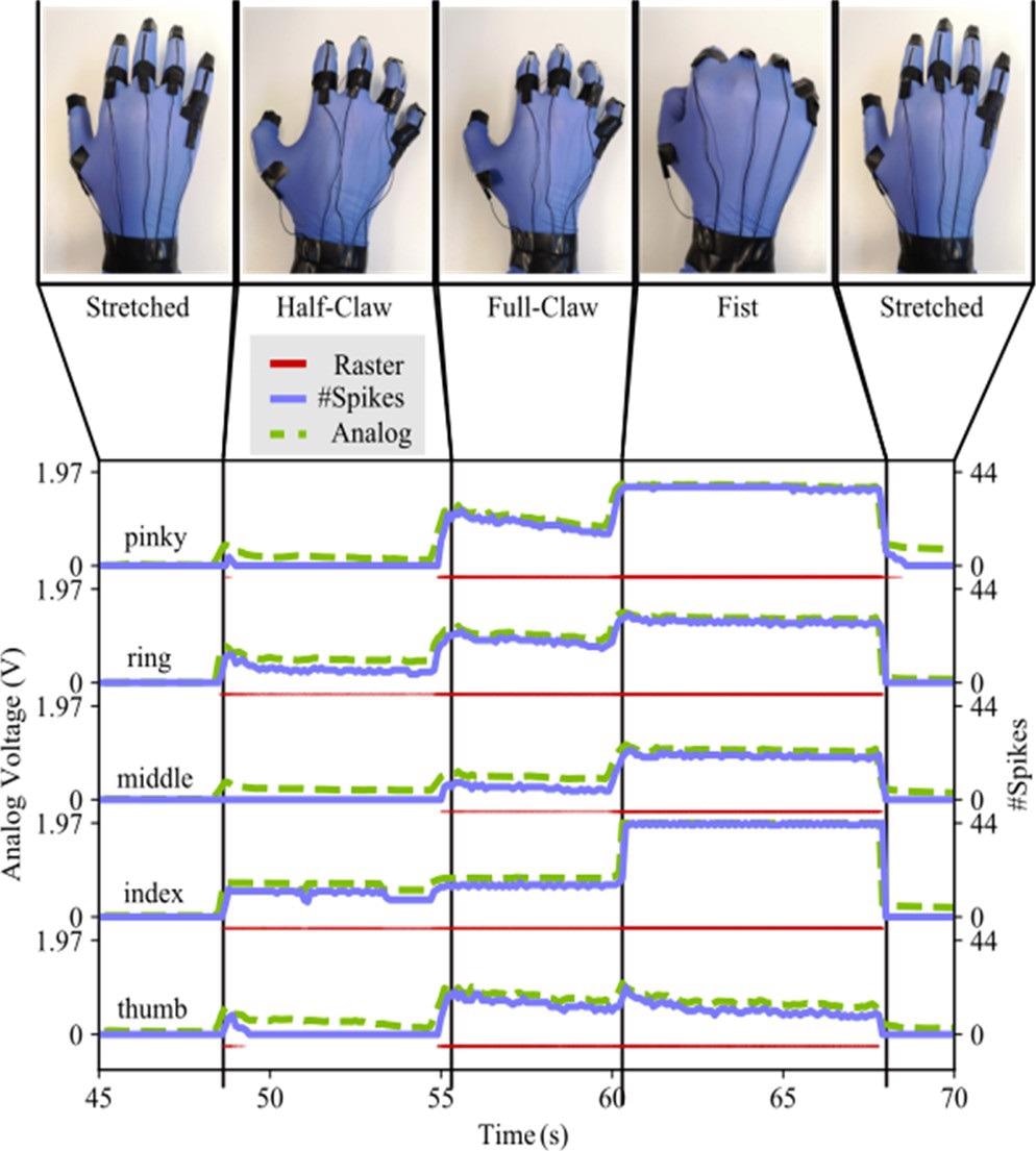
Figure 5. Response of the five sensors and the five neurons to various hand gestures. The sensor output voltage sensors increase with the increasing curvature of the finger, and the neuron response follows this behavior. Image Credit: Sengupta, et al., 2022
Methodology
To prepare a 9% (w/v) PAN polymer solution in DMF for electrospinning, Sigma-Aldrich provided polyacrylonitrile (PAN) powder (150,000 g/mol) and N, N-dimethyl formamide (DMF). Electrospinning was completed using an Inovenso NanoSpinner NE300.
Tactile sensing and gesture monitoring tests required the development of resistance-matched Wheatstone bridge circuits to which the CNF-PDMS sensors were coupled. Brian2, a spiking neural network simulator, was used to convert the sensors’ voltage acquired during various trials. In this study, we focused on two main cases: rate encoding and spatial encoding.
The neurons that encoded the five separate sensors were synapsed to five different output neurons in a second layer in this study. Synapses are electrical components that translate the voltage differential in a neuron's spike into a current.
Conclusion
Researchers suggested a combined strategy to encode proprioception and tactile information using innovative CNF-PDMS-based piezoresistive sensors and spiking neural networks without the need for digital structures such as analog-to-digital converters or digital signal processing in this paper.
The developed piezoresistive sensor is utilized to transform several forms of inputs, such as touch sensors or strain sensors, into spikes, demonstrating how the number of pulses released by a neuron may transmit analog values such as tactile pressure or deformation.
Importantly, the potential behind this has been shown in the study, which demonstrates how neural networks can decipher the information contained in the sensors’ responses without the need for any digital processing, as in gesture recognition.
The final architecture includes a direct link between sensors and the neural network. CMOS circuits can considerably enhance the ability of robots, autonomous agents, or prosthetic devices to detect complex inputs, resulting in low power consumption and low latency conversion, as seen in embedded techniques.
Journal Reference:
Sengupta, D., Mastella, M., Chicca, E., Kottapalli, A. G. P. (2022). Skin-Inspired Flexible and Stretchable Electrospun Carbon Nanofiber Sensors for Neuromorphic Sensing. ACS Applied Electronic Materials, 4(1), pp. 308–315. Available Online: https://pubs.acs.org/doi/10.1021/acsaelm.1c01010.
References and Further Reading
- Amjadi, M., et al. (2015) Ultra-Stretchable and Skin-Mountable Strain Sensors Using Carbon Nanotubes–EcoflexNanocomposites. Nanotechnology, 26, p. 375501.doi.org/ 10.1088/0957-4484/26/37/375501.
- Qin, Y., et al. (2015) Mechanically Flexible Graphene / Polyimide Nanocomposite Foam for Strain Sensor Application. ACS Nano, 9, pp. 8933–8941. doi.org/10.1021/acsnano.5b02781.
- Pang, Y., et al. (2016) Flexible, Highly Sensitive, and Wearable Pressure and Strain Sensors with Graphene Porous Network Structure. ACS Applied Materials & Interfaces, 8, pp. 26458–26462. doi.org/10.1021/acsami.6b08172.
- Boland, C. S., et al. (2014) Sensitive, High-Strain, High-Rate Bodily Motion Sensors Based on Graphene–Rubber Composites. ACS Nano, 8, pp. 8819–8830. doi.org/10.1021/nn503454h.
- Sharma, S., et al. (2020) Wearable Capacitive Pressure Sensor Based on MXene Composite Nanofibrous Scaffolds for Reliable Human Physiological Signal Acquisition. ACS Applied Materials & Interfaces, 12, pp. 22212–22224. doi.org/10.1021/acsami.0c05819.
- Huang, T., et al. (2019) Porous Fibers Composed of Polymer Nanoball Decorated Graphene for Wearable and Highly Sensitive Strain Sensors. Advanced Functional Materials, 29, p. 1903732. doi.org/10.1002/adfm.201903732.
- Sengupta, D., et al. (2020) Single and Bundled Carbon Nanofibers as Ultralightweight and Flexible Piezoresistive Sensors. npj Flexible Electronics, 4, p. 9.
- Sengupta, D., et al. (2020) Piezoresistive Carbon Nanofiber-Based Cilia-Inspired Flow Sensor. Nanomaterials, 10, p. 211. doi.org/10.3390/nano10020211.
- Streri, A (1987) Tactile Discrimination of Shape and Intermodal Transfer in 2- to 3-Month-Old Infants. British Journal of Developmental Psychology, 79, p. 618. doi.org/10.1111/j.2044-835X.1987.tb01056.x.
- Abraira, V E & Ginty, D D (2013) The Sensory Neurons of Touch. Neuron, 79, p. 618. doi.org/10.1016/j.neuron.2013.07.051.
- Yi, Z., et al. (2018) Biomimetic Tactile Sensors and Signal Processing with Spike Trains: A Review. Sensors and Actuators A, 269, p. 41. doi.org/10.1016/j.sna.2017.09.035.
- Kim, E. K., et al. (2012) Force Sensor in Simulated Skin and Neural Model Mimic Tactile SAI Afferent Spiking Response to Ramp and Hold Stimuli. Journal of NeuroEngineering and Rehabilitation, 9, p. 45.doi.org/10.1186/1743-0003-9-45.
- Bologna, L. L., et al. (2013) A Closed-Loop Neurobotic System for Fine Touch Sensing. Journal of Neural Engineering, 10, p. 046019. doi.org/10.1088/1741-2560/10/4/046019
- Lee, W. W., et al. (2013) Bio-Mimetic Strategies for Tactile Sensing. SENSORS, 2013 IEEE. doi.org/10.1109/ICSENS.2013.6688260.
- Hatzfeld, C., et al. (2012) Perception-Inspired Haptic Force Sensor - A Concept Study. Procedia Engineering, 47, p. 112. doi.org/10.1016/j.proeng.2012.09.097.
- Kayser, C., et al. (2009) Spike-Phase Coding Boosts and Stabilizes Information Carried by Spatial and Temporal Spike Patterns. Neuron, 61, p. 597. doi.org/10.1016/j.neuron.2009.01.008.
- Lee, W. W., et al. (2014) Gait Event Detection through Neuromorphic Spike Sequence Learning. Proceedings of the IEEE RAS and EMBS International Conference on Biomedical Robotics and Biomechatronics. doi.org/10.1109/BIOROB.2014.6913895.
- Chou, T.-S., et al. (2015) Learning Touch Preferences with a Tactile Robot Using Dopamine Modulated STDP in a Model of Insular Cortex. Frontiers in Neurorobotics, 9, p. 6. doi.org/10.3389/fnbot.2015.00006.
- Parvizi-Fard, A., et al. (2021) A Functional Spiking Neuronal Network for Tactile Sensing Pathway to Process Edge Orientation. Scientific Reports, 11, p. 1320. doi.org/10.1038/s41598-020-80132-4.
- Dabbous, A., et al. (2021) Artificial Bio-Inspired Tactile Receptive Fields for Edge Orientation Classification. 2021 IEEE International Symposium on Circuits and Systems (ISCAS). Institute of Electrical and Electronics Engineers, pp. 1–5. doi.org/10.1109/ISCAS51556.2021.9401749.
- Osborn, L. E., et al. (2018) Prosthesis with NeuromorphicMultilayered E-Dermis Perceives Touch and Pain. Science Robotics, 3, p. eaat3818. doi.org/10.1126/scirobotics.aat3818.
- Simmons, J G (1963) Generalized Formula for the Electric Tunnel Effect between Similar Electrodes Separated by a Thin Insulating Film. Journal of Applied Physics, 34, pp. 1793–1803. doi.org/10.1063/1.1702682.
- Yu, Y., et al. (2010) Determinant Role of Tunneling Resistance in Electrical Conductivity of Polymer Composites Reinforced by Well Dispersed Carbon Nanotubes. Journal of Applied Physics, 108, p. 084319. doi.org/10.1063/1.3499628.
- Boujamaa, E. M., et al. (2010) A Low Power Interface Circuit for Resistive Sensors with Digital Offset Compensation. ISCAS 2010: 2010 IEEE International Symposium on Circuits and Systems, Nano-Bio Circuit Fabrics and Systems, pp. 3092–3095. doi.org/10.1109/ISCAS.2010.5537970.
- Saxena, R. S., et al. (2009) A New Discrete Circuit for Readout of Resistive Sensor Arrays. Sensors and Actuators A, 149, pp. 93–99. doi.org/10.1016/j.sna.2008.10.013.
- Abbott, L F (1999) Lapicque’s Introduction of the Integrate-and-Fire Model Neuron. Brain Research Bulletin, 50, pp. 303–304. doi.org/10.1016/S0361-9230(99)00161-6.
- Cassidy, A & Andreou, A G (2008) Dynamical Digital Silicon Neurons. 2008 IEEE-BIOCAS Biomedical Circuits and Systems Conference, BIOCAS 2008, pp. 289–292.
- Han, J., et al. (2020) Hardware Implementation of Spiking Neural Networks on FPGA. Tsinghua Science and Technology, 25, pp. 479–486. doi.org/10.26599/TST.2019.9010019.
- Floreano, D., et al. (2005) From Wheels to Wings with Evolutionary Spiking Circuits. Artificial Life, 11, pp. 121–138. doi.org/10.1162/1064546053278900.
- Chicca, E., et al. (2014) Neuromorphic Electronic Circuits for Building Autonomous Cognitive Systems. Proceedings of the IEEE, 102, p. 1367. doi.org/10.1109/JPROC.2014.2313954.
- Rubino, A., et al. (2019) Ultra-Low Power Silicon Neuron Circuit for Extreme-Edge Neuromorphic Intelligence. 2019 26th IEEE International Conference on Electronics, Circuits and Systems, ICECS 2019, pp. 458–461. doi.org/10.1109/ICECS46596.2019.8964713.
- Indiveri, G., et al. (2011) Neuromorphic Silicon Neuron Circuits. Frontiers in Neuroscience, 5, p.73. doi.org/10.3389/fnins.2011.00073.
- Stimberg, M., et al. (2019) Brian 2, an Intuitive and Efficient Neural Simulator. Elife, 8, p. e47314. doi.org/10.7554/eLife.47314.001.