Ultrasonic sensors are the preferred choice for a broad range of non-contact distance measuring applications. They are often regarded as the most economical devices for applications like liquid level measurement in tanks.
Ultrasonic sensors are engineered specifically for installation into an NPT threaded hole at the top portion of a tank. These sensors usually lack the ability to detect targets located closer than 4 inches within the face of the transducer.
Several applications present headroom constraints, for example, a drainage tube, where it is preferred to mount a sensor with a thin, small housing that can fit onto the top inner side surface of a container or pipe and quantify the distance to the material inside when it is quite closer than 4 inches within the transducer’s face.
Although ultrasonic sensors are good at measuring the distance to smooth surfaces, like still liquids, they often present problems while detecting target echoes arising from uneven surfaces, for example, solid materials or turbulent liquids. Proper insights into the acoustics in the system design can help overcome such problems.
Operation of Typical Ultrasonic Sensors
The two-part article titled “Choosing an Ultrasonic Sensor for Proximity or Distance Measurement,” penned by the author of this article and published in the February and March 1999 editions of Sensors Magazine (users can obtain a reprint at www.massa.com/about/publications), offers a more comprehensive overview of the basics of ultrasonic sensors.
The above-mentioned article notes that ultrasonic sensors produce a short pulse of several hundred volts, often containing 10 to 20 cycles, applied to an electroacoustic transducer. The transducer converts the electrical signal into a short tone burst of sound.
This ultrasonic pulse moves from the transducer’s surface through the air to the to-be-measured material. When the sound pulse gets reflected from the target’s surface, the echo returns to the transducer.
Here, where it is transformed into an electrical signal and detected by the electronic circuit of the sensor, which measures the time taken from the sound pulse generation until the return of the echo. The sensor calculates the distance to the target by using the speed of sound.
Figure 1 shows a typical ultrasonic sensor fitted on a tank to quantify the liquid level within the tank. The sensor includes a single ultrasonic transducer that produces a sound pulse that moves over an extremely narrow beam angle, which is essentially 10°, to the liquid surface. When the reflected echo returns to the transducer, it is detected.
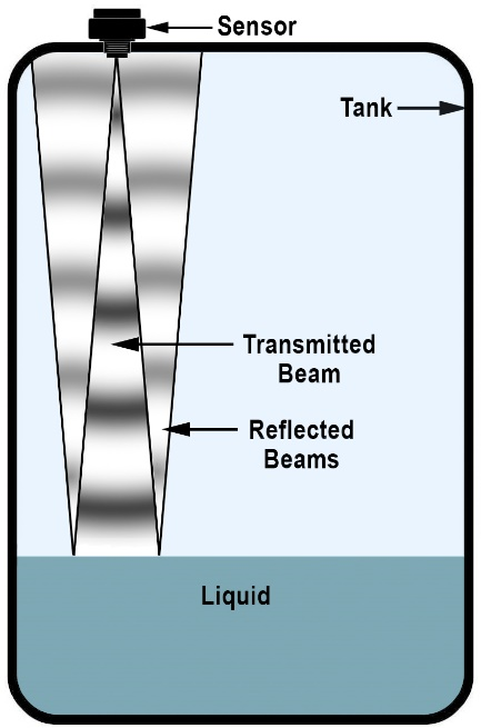
Figure 1. Illustration showing an ultrasonic sensor mounted on a tank transmitting a conical ultrasonic beam that reflects from the liquid surface. Image Credit: Massa Products Corp.
Excitation of the transducer using the large electric drive signal makes it 'ring' like a bell once the high voltage pulse is cut off. This voltage takes a long time across the transducer to minimize to a level below the voltage produced by the echo reflected from the liquid surface.
This time governs the minimum distance from which a target can be detected from the transducer, which is usually greater than 4 inches.
The sound pulse arising from the sensor generates a distinct echo from a smooth liquid surface. But a turbulent surface—the irregular surface produced by solid material within the tank—can cause scattering of the reflected, making it difficult to be accurately detected by a sensor with a narrow beam angle.
A wider beam angle will generate detectable echoes. Solid material, for example, grain, contained in the tank can develop a sloped surface, rather than the flat level surface formed by a liquid. This can make the sound beam reflect away from the sensor, rendering the echo undetectable.
Figure 2 depicts two tanks that include a solid material, for example, grain, with a somewhat sloped surface caused by the entry of the grain into the tank from the top.
Figure 2a illustrates how the echo from a narrow beam sensor is reflected from the material’s sloped surface in the tank away from the transducer, which makes it undetectable.
Figure 2b illustrates the echo returning from a wider beam sensor to the transducer after it is reflected from the material’s same sloped surface within the tank, which makes it detectable.
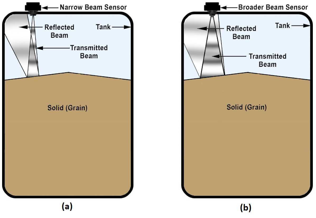
Figure 2. Illustration showing a narrow beam sensor and a broader beam sensor mounted on tanks with their conical beams reflecting from the sloped surface of solid material such as grain. (a) Narrow beam reflects away from sensor and echo is undetected. (b) Broader beam reflects back to sensor and echo is detected. Image Credit: Massa Products Corp.
Designing Ultrasonic Sensors with Close Target Detection Ranges and Detectable Echoes from Uneven Surfaces
For mounting an ultrasonic sensor within a pipe or container that needs a very short detection range, or if it has to detect echoes reflected from irregular surfaces, it should be designed specifically for these purposes.
The MassaSonic™ FlatPack™ Series of Sensors constitute an example of such a sensor and have recently been launched by Massa Products Corporation.
Figure 3 depicts the snapshot of a FlatPack™ Sensor. From the figure, it is evident that the electronics package has been engineered for a very shallow profile for easy mounting on top of a tank or pipe with the faces of the transducers within an inch below its mounting surface. Also illustrated is that the sensor includes two transducers.
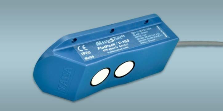
Figure 3. Photograph of a MassaSonic™ FlatPack™ ultrasonic sensor showing its shallow profile package and dual transducers, making it ideal for very close range detection of levels near the top of pipes and containers. Image Credit: Massa Products Corp.
One of the transducers transmits an ultrasonic pulse, and the other one detects the returned echo. The receiving transducer is not linked to the large electrical drive signal, hence a large voltage is not produced across it when the acoustic pulse is generated.
Thus, it can detect the small voltage generated by the return echo while the transmitting transducer still 'rings' with a large voltage across it. Hence, this enables the sensor to detect an echo that returns from a target located within 1 inch.
The transducers fitted in the FlatPack™ are also engineered to create wider patterns featuring beam angles twice as large as those of other standard ultrasonic sensors. This enables it to detect echoes from irregular surfaces, for example, solid materials and turbulent liquids, which cannot be detected by other sensors.
Conclusions
Proper designing of ultrasonic sensors enables them to serve close target detection ranges and produce powerful echoes from irregular surfaces. It is essential to design the sensors with two transducers—one to transmit an ultrasonic pulse and the other to detect the echo returned from the surface being measured.
The sensor’s housing must have a low profile. The ultrasonic transducers must also be engineered to generate wider beam angles to make sure that echoes returned from irregular surfaces are reflected back to the sensor and detected.
Ultrasonic sensors with such a design are perfect for use in applications like conveyors, pipes, tanks, conduits, or hoppers and can detect echoes from turbulent pastes liquids, solids, or powders at ranges within 1 inch.

This information has been sourced, reviewed and adapted from materials provided by Massa Products Corp.
For more information on this source, please visit Massa Products Corp.