Shock and vibration can be characterized in terms of variations in displacement, velocity or acceleration with time.
Acceleration is the most commonly used since the inertial load or destructive force is equal to mass times acceleration:
The maximum destructive force (Fm) is acquired from:
Where W = weight of the specimen and G = the maximum acceleration in gravity units.
Acceleration, velocity and displacement measurements can only correlate easily when the vibration under investigation is a basic sinusoidal motion containing just one frequency.
However, the vibratory motions measured in practice are nearly always comprised of some harmonic distortion, even with sinusoidal laboratory shakers. Thus, if acceleration data is required, a transducer with the ability to identify acceleration should be used.
No attempt should be made to correlate velocity and displacement data without carefully considering the calculations that are necessary for complex wave motion.
Application Information
Measuring shock and vibration phenomena accurately requires a good understanding of the transducer and the electronic equipment required in terms of the dynamic response as a system.
Often, historical records show critical errors (in some cases by a factor as much as 100 times) that have emerged during test work as a result of the spurious output of the measuring instrumentation.
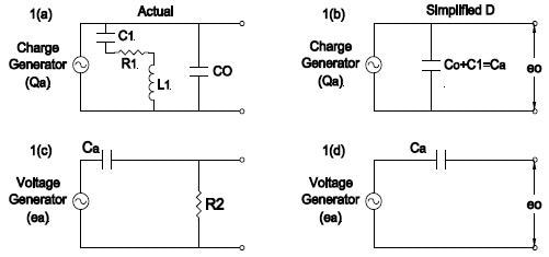
Figure 1. Two Equivalent Circuit-Forms for Piezoelectric Transducers. Image Credit: Columbia Research Laboratories
The wide dynamic responses of the Columbia Accelerometer and Instrumentation design is equipped with the capacity to handle almost any problem that emerges, with accelerations ranging from .001 to 40,000 g at frequencies from 1 to 15,000 cps. Thereby significantly reducing the potential of errors that tend to result in the failure of the measuring system.
Accelerometer Equivalent Circuits
Possessing knowledge of the equivalent circuits for a piezoelectric transducer can be extremely useful when trying to understand the problems associated with their use. The accelerometer could be considered either a charge generator or a voltage generator. Both circuits are displayed in the actual and simple form below.
Since the accelerometer’s operating frequencies are comparatively low, only the capacitive reactance is appreciable against the inductive reactance and resistance.
In 1(b) a charge qa is produced across the crystal faces for any acceleration measurement given. The voltage eo out of the accelerometer is:
Where Ca represents the capacitance of the accelerometer. The charge generated as qa per unit of acceleration is independent of any shunting capacity.
In 1(d), a voltage ea is generated for any given acceleration measurement across the crystal faces. It is thus evident that voltage eo out will fluctuate in relation to the external shunting capacity.
Coulomb or Charge Sensitivity
Each Columbia accelerometer is equipped with a calibration card that states the sensitivity in pCMB/G. The charge sensitivity Sq can be taken using Eq. (3) if the total shunting capacity Cs is known. The expression is as follows:
| Sq = S(Ca + Cs) x 10‐3 (coulombs) / (peak g) |
(Eq.4) |
Where S = the peak voltage output eo (peak) divided by the peak acceleration g in gravity units, that is, S represents the factory-calibrated sensitivity in peak millivolts per peak g calibrated with 100 pF total external shunting capacitance.
Cs is the whole external shunting capacitance of 100 pF and Ca indicates the crystal capacitance in pF
Substituting for Cs in Eq.(4) the relation can be drawn from the following equation:
| Sq =S(Ca + 100) x 10‐3 (coulombs) / (peak g) |
(Eq.5) |
Voltage Sensitivity
The voltage sensitivity vs. frequency is also apparent on every calibration card. This calibration S is made with precisely 100 pF of total external shunting capacitance across the accelerometer output.
The sensitivities are highlighted as peak millivolts per single peak g. The root mean square sensitivity S(RMS) is S/1.41. When accelerometer output is measured on an RMS VTVM, S(RMS) should be used for the calibration value.
When it is more convenient to make measurements of single peak voltage on meters or oscillographic records, apply S for the accelerometer sensitivity. If measuring peak-to-peak voltages, use 2xS for the calibration sensitivity. The open circuit sensitivity So can be established using the sensitivity S with the following equation:
| So = S (Ca = 100) / Ca |
(Eq.6) |
Effect of Cables and Capacity on Accelerometer Sensitivity
When placing any capacity in the form of cables, connectors or input capacitance of the matching amplifier or cathode follower on the output of the accelerometer – other than the 100 pF factory calibration – then corrections must be made to establish the sensitivity S.
The new sensitivity S1 may be determined using the equation:
| S1 = S (Ca + 100)/(Ca + Cs) (peak mv) / (peak g) |
(Eq.7) |
Where S stands for the factory-supplied voltage sensitivity in peak mv/peak g with 100 pF total external shunting capacitance. Ca represents crystal capacitance in pF Cs is the total external capacitance, including the cable in pF.
S1 becomes the updated sensitivity for any total shunting capacitance Cs.
Normalization of Accelerometer Sensitivity
COLUMBIA amplifiers come readily fitted with input shunt capacitors and variable gain controls that facilitate the standardization of accelerometer sensitivities. The input shunt capacitors are comprised of a variable capacitor in combination with fixed capacitors.
The variable trim capacitor enables the standardization of a number of accelerometer sensitivities to a single value so that a direct readout on a VTVM scale can be conveniently made in g. For instance, if a 12 rms mv/ peak g accelerometer is standardized to 10 rms mv/peak g then a full-scale setting of 0.1 rms volt will represent 10 g for full-scale deflection.
This generally allows reading from 0.1 g to 10 g. The fixed capacitors enable a reduction in sensitivities up to 10 and 100 times for higher g‐level shock work in the 1000 g range, where there may be an exceeding of the 10‐20 overload voltage limit of the amplifiers.
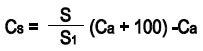
The capacity required for standardization to a particular value can be established by solving for Cs in Eq. 8.
 |
(Eq.8) |
Charge Amplifier
Figure 2. illustrates a functional circuit of a transducer charge amplifier system. In this amplifier, the capacitive component of the input impedance completely differs from a cathode or emmiter follower where the resistive component is extremely high.
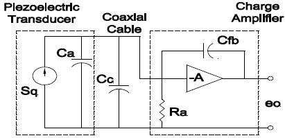
Figure 2. Image Credit: Columbia Research Laboratories
The equivalent capacitance may behave in a manner akin to the well-known Miller effect. The amplifier draws its high capacitive component through negative feedback and is proportional to the open loop gain of the amplifier. Therefore, the effect input capacitance of the amplifier is represented using the equation:
Due to the fact that the gain is typically large, that is A>>1, the input capacitance is more or less equal to Cfb multiplied by A. The higher input resistance Ra is conceived by the use of field-effect transistors in the input stage.
The combination of high input capacitance and high input resistance leads to the capacity to generate an extremely low frequency response with smaller transducer capacitances, represented by the equation:
 |
(Eq.10) |
The total charge gain of the amplifier can be determined as:
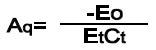 |
(Eq.11) |
While the charge gain of the amplifier relative to volts output/pcmb input is shown as:
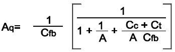 |
(Eq.12) |
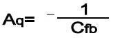
Typically, ACfb>CC + Ct and A>>1, which means that the equation above can be re-represented as:
 |
(Eq.13) |
Indicating the charge gain is inversely proportional to minus the feedback capacitance.
Transducers
Ideally, transducers should be isolated from grounding by a minimum of 10 MΩ. Where a grounded transducer is used, noise pick‐up from ground currents in the structure under test may hinder accurate measurements of low level signals.
When this situation emerges, it may be necessary to introduce an “insulating stud” or other method for appropriate isolation of the transducer from the grounded structure. Transducers utilized with the charge amplifiers must display capacitive impedance relative to the input of the amplifier.
Resistive shunting to ground will have an adverse influence on the amplifier operation. If the shunt resistance drops to around 50 MΩ, there will be a shift in amplifier DC bias until at some point the value of shunt resistance of the amplifier will become redundant.
If it is deemed necessary to include a device that cannot preserve the minimum shunt resistance required, a scheme as displayed in Fig. 3 can be introduced. The capacitor Cs must be a very low leakage type, such as a film capacitor or high quality tantalum.
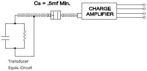
Figure 3. Image Credit: Columbia Research Laboratories
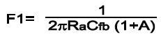
A further consideration to take into account when employing a low shunt resistance capacitive device is the deterioration of the low frequency response due to the RC time constant formed. The –3db response point is determined by the equation below:
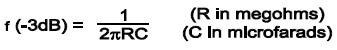 |
(Eq.14) |
The –5% response point is roughly 3X the –3db frequency.
Frequency Response Characteristics of Crystal Accelerometers
The piezoelectric pick-up response accuracy to a vibratory or shock motion is of utmost importance. Typically, the lower frequency response is restricted by electrical parameters and as a consequence, is distinguished from electrical considerations.
There is generally a limitation imposed upon upper-frequency response due to the first mechanical resonance of the accelerometer system, which is consequently derived from calculations predicated on the mechanical characteristics.
Lower Half Power Cut‐Off Frequency
The crystal-type accelerometer demonstrates a low frequency response which corresponds to the RC time constant of the accelerometer and the matching electronics.
A common pick‐up with a crystal capacitance of 580 pF must be able to function into a high input impedance of 100 MΩ or more when employed with VTVM in order to acquire a satisfactory frequency response below 100cps.

This information has been sourced, reviewed and adapted from materials provided by Columbia Research Laboratories, Inc.
For more information on this source, please visit Columbia Research Laboratories, Inc.