The servo force balance accelerometer can deliver exceptional performance and accuracy with a number of advantages. This fact is clearly demonstrated by their extensive use in applications requiring 0.1% or better overall accuracy.
Unlike traditional accelerometers, the servo type incorporates a freely suspended mass bound by an electrical equivalent mechanical spring. There are two classes of servo force balance accelerometers: the pendulous type, which has an unbalanced pivoting mass with angular displacement, and the non‐pendulous type, which is mass displaced linearly.
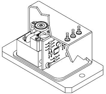
Figure 1. Force Balance Sensor. Image Credit: Columbia Research Laboratories
The behavior of all accelerometers can be explained by Newton’s second law of motion:
Force = mass x acceleration: F = ma
This equation demonstrates that if a mass is to be accelerated, a force relative to the amount of acceleration must also exist. If the force can be determined, the amount of acceleration can be measured.
For pendulous type accelerometer, the polar form of the equation applies:
Torque = pendulous mass x acceleraton: T = (ml)a
Where (l) represents the distance from axes of rotation to the center of mass, and (ml) is the pendulous mass.
Why Choose a Force Balance Sensor?
The force balance sensor is geared towards DC and low frequency acceleration measurements, such as those found in the motion of vehicles, aircraft and ships. These sensors have the capacity to measure levels from as low as 0.0001 g up to 200 g across a frequency range from DC to 1000 Hz.
Additionally, due to their innate sensitivity to gravity, making specific modifications or introducing special features to the force balance accelerometers makes them excellent instruments for measuring angles of inclination.
This kind of sensor, generally known as an inclinometer, is practical for use in applications such as borehole mapping, gun sight control, platform leveling, pipeline leveling and other low level seismic measurement applications.
Advantages
The force balance sensor offers a number of advantages that produce excellent performance in the aforementioned applications. Internal displacements within any accelerometer generate inaccuracies and errors typically in the form of disproportionate levels of hysteresis, stickiness, non‐linearity and non‐repeatability.
LVDT, potentiometric, variable reluctance and similar kinds of sensors all have the potential to cause these errors, which results from the fact that the sensing element must travel over some distance in order to generate a measurable change in output.
Conversely, the output signal from a force balance accelerometer is not contingent on the displacement of some internal element being a linear function of acceleration. Internal displacements remain comparatively small, generally less than one ten-thousandth of an inch.
In addition to minimizing static error, the minute displacements relative to the force balance sensor contribute to the relatively high natural frequency this type of sensor possesses. A strain gage sensor does not necessitate excessive internal displacements but is vulnerable to effects of temperature, creep and aging, which can result in instability.
Opposed to other low frequency accelerometers, which need viscous media, dash pots or similar mechanical damping techniques, the force balance senor’s dynamic response can be damped and adjusted with ease to a specific value by way of electronic networks.
The damping ratio can be calibrated to near critical for a maximum usable response or to a higher degree or limited response and sensitivity to high frequencies.
Generally, in open loop types of transducers, the ratio is either controlled by means of viscous media or uncontrolled, as in the case of piezoelectric devices. In the former case, it is not possible to control the damping ratio by any tight tolerances due to viscosity changes vs. temperature.
A number of strain gage, potentiometric or LVDT type accelerometers incorporate thermostatically controlled heaters in an attempt to stabilize damping characteristics.
Additionally, in most cases, the force balance accelerometer is completely self-controlled, which means additional signal conditioning is not necessary, which means they have the capacity to directly interface with spectrum analyzers, oscilloscopes, data acquisition systems, digital voltmeters and displays.
The full-scale output is typically in the order of several volts and necessities no additional amplification.
How the Force Balance Sensor Works
The force balance sensor is comprised of a position detector, albeit not one that is necessarily linear, as well as an amplifier and an electromechanical system. This combination facilitates the conversion of a mechanical force into a proportional current which then converted back into an equal opposing mechanical force.
The position of a mass paired with the force generator can be tracked using the position detector. A change in mass position, which is externally induced, results in a combination position detector, amplifier output such as that the force generator drives the mass back to its original position.
The output of the sensor is a measure of the current through the force generator, this current being proportional to the restoring force, which is equivalent to the input force through the calibrated mass (see to Fig. 2). With no acceleration, the current through the force generator is zero.
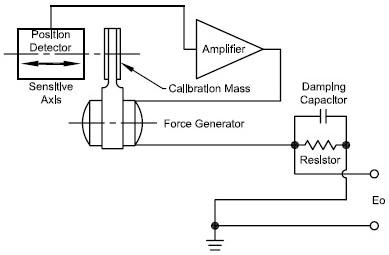
Figure 2. Black Diagram of Force Balance Sensor. Image Credit: Columbia Research Laboratories
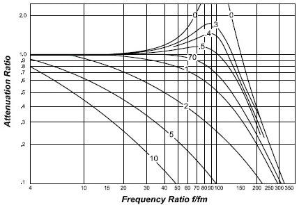
Figure 3. Frequency Response. Image Credit: Columbia Research Laboratories
The force generator current can be monitored using a resistor in series, thereby generating a voltage output exactly proportional to the original mechanical input. The electronic damping is facilitated by a capacitor and positioned across the sampling resistor.
The capacitor and sampling resistor make up a lead network which leads to an overall reduction of the amplifier voltage at high frequencies necessary to drive the restoring current.
The Columbia “HP” (High Performance Torquer)
A force balance accelerometer necessitates a suspended mass to effectively translate acceleration into a measurable force. There must be a means to apply a current through a coil in a magnetic circuit for the purpose of balancing out the force caused by the applied acceleration. In force balance circles, this assembly is referred to as a forcer or torquer.
One of the most critical aspects of a torquer is the technique employed to support the mass. Preferably, the means of support should enable the mass to move in only a single, well-defined direction and, at the same time, eradicate motion in remaining across axis directions.
Also, the support should not introduce its own forces, such as friction or spring effects. The mass support must also be robust enough to endure the required physical environments without degrading.
Three methods are frequently employed by accelerometer manufacturers. They include flexures, taut bands and bearing. The flexure and taut band system possess similar advantages and drawbacks. They are effectively frictionless and thus produce exceptional repeatability.
The flexure has exceptional sensitive axis definition, while the taut band is prone to sagging under cross axis loading and should be supported in fluid as to limit its sensitivity to cross loads and vibration. Both are vulnerable to damage from shock.
Metal flexures can experience permanent deformation, which can cause zero bias errors, while brittle non‐metallic flexures fracture and catastrophically fail under the same conditions.
Stiff flexures also create non‐linear output characteristics due to their tendency to self‐restore. This non‐linearity is not clear in bearing-type accelerometers. CRL accelerometers utilize bearings to support a pendulous mass.
The most economical CRL accelerometer employs a pivot and jewel bearing. This system is ideal for applications where cost is a primary concern and accuracy and environmental requirements are not determining factors.
The more complex CRL accelerometers utilize high performance all bearing suspension in place of the pivot and jewel. The physical tolerances of these bearings are around twenty times tighter than those of a conventional pivot and jewel bearing.
Their performance is up there with the very best flexures, and they will also survive in adverse environments enduring excessive shock and vibration.
Other advantages that the COLUMBIA “HP” TORQUER include low rectification, no pivot‐flop, no progressive deterioration and exceptional static performance under vibration. All basic and “HP” torquer models are manufactured entirely at CRL to guarantee consistent “unit to unit performance” and reliability.
Explanation of Characteristics
The following section outlines a number of specifications which should assist in the assessment and selection of force balance sensors for specific applications.
Scale Factor
Scale Factor is the ratio of a change in output to a variance in the input intended to be measured or applied.
The scale factor calibration featured in CRL accelerometers is expressed volts/g or volts/radian/sec².
The inclinometer’s scale factor is also expressed in volts/g. However, it must be employed in parallel with the equation:
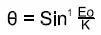
To determine the measured angle, Eo is the measured output and K represents the output at 90° or one g (see Fig. 4). Conversion is not necessary when the inclinometer is used with a CRL DVM calibrated to read directly in degrees.
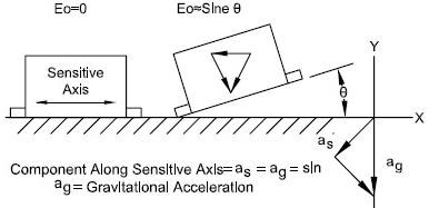
Figure 4. Scale Factor. Image Credit: Columbia Research Laboratories
Bias
Bias is the measured sensor output when there is no application of mechanical input.
Input Axis
An input axis is an axis along which an acceleration or inclination of the case results in maximum output.
Cross Axis Sensitivity
Cross axis sensitivity describes the proportionally constant relative to the variation of accelerometer and inclinometer output to cross acceleration or inclination.
Composite Error
Composite error is the maximum deviation of the output data from the determined output function. Composite error can include the effects of hysteresis, resolution, non‐linearity, non‐repeatability and other uncertainties in the output data. It is typically expressed as a percentage of the output range.
Repeatability
Repeatability refers to the property of a sensor to reproduce a given output of performance characteristics under identical input and environmental conditions. Repeatability incorporates the effects of threshold, resolution and uncertainties in other performance characteristics.
Non‐Linearity
Non‐linearity refers to the deviation of the output data from the straight line determined by the zero input bias and scale factor coefficient (see Figure 5).
Hysteresis Error
Hysteresis error refers to the difference between output signals for increasing and decreasing inputs at that input for which the difference is maximum measured after cycling through the input scan (see Figure 5).
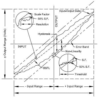
Figure 5. Input-Output Characteristics of a typical Force-Balance Accelerometer. Image Credit: Columbia Research Laboratories
Resolution
Resolution refers to the greatest value of the minimum change in input for inputs more than the threshold, which yields a change in output equal to some distinct percentage (at least fifty percent) of the change in expected output utilizing the nominal scale factor (see Figure 5).
Threshold
Threshold refers to the greatest absolute value of the minimum input that generates an output equal to some specific percentage (at least fifty percent) of the anticipated output using the nominal scale factor (see Figure 5).
Rectification Error
Rectification error refers to a steady-state error in the output caused by the vibratory disturbances that act on an accelerometer or inclinometer.

This information has been sourced, reviewed and adapted from materials provided by Columbia Research Laboratories, Inc.
For more information on this source, please visit Columbia Research Laboratories, Inc.