For modern control systems, position sensors are a vital feature. While in many instances, the failure of a position sensor may have no impact on safety, in other cases, such a failure could have disastrous results.
.jpg)
In this paper are several design methods that engineers should implement in relation to position sensors to guarantee the safe and dependable operation of equipment.
To begin, it is important to define relevant terms clearly. Within this article, the term ‘position sensor’ will be used to describe devices such as transducers, encoders and transmitters that measure the angle, linear displacement, angular or linear speed and which put out a corresponding electrical signal.
These devices can take many formats, including potentiometers, resolvers and inductive and optical encoders.
The term ‘failure’ should also be carefully defined. Within this paper, three types of failure will be referred to:
- No output – The sensor ceases to report its output signal, either sporadically or permanently
- Incorrect output with error flag – output from the sensor is inaccurate, but inaccuracy is detected by the sensor
- Incorrect output with no error flat – output from the sensor reports an incorrect position, but sensor does not detect an inaccuracy
The most serious variety of failure is usually type three.
The terms ‘safety-relevant’ and ‘safety-critical’ are also useful, and despite commonly being mistakenly conflated, should not be used interchangeably. Safety relevant typically refers to a case where there may be some safety implications arising from the position sensor failure, while safety-critical typically refers to cases in which failure has significant safety implications.
Intrinsic safety is another commonly used term, and denotes sensors, which are employed in potentially hazardous or explosive environments. Intrinsically safe sensors inhibit ignition in these atmospheres through several techniques, including encapsulation, sensor packaging and limited the amount of stored energy. However, it is not of great relevance to this piece.
Safety-Related Applications
When developing any safety-related application that incorporates a position sensor, it is helpful to imagine a spectrum ranging from no safety relevance to safety-critical. With greater degrees of safety relevance, the most suitable sensor arrangement changes.
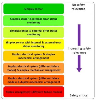
Figure 1. A spectrum of design approaches for position sensors as safety demands increase. Image Credit: Celera Motion
It should also be considered that in general, greater safety relevance correlates with a more costly solution.
Applications without any safety relevance are reasonably simple. For example, the failure of a potentiometer controlling the volume of a domestic radio would generally result in only a small inconvenience, and thus it is unnecessary to monitor the potentiometer’s performance.
With greater safety relevance, the first stage for an engineer is to employ a sensor to carry out self-diagnostics, often known as the Built-In-Test or BIT. Where the sensor’s internal diagnostic tests detect failure, the sensor outputs an error flag in addition to or instead of its output signal.
These error flags can take several forms. For example, in an analog sensor with a 0.5 to 10 V output, the output can be lowered to <0.5 V to indicate an error signal. Likewise, devices such as modern inductive encoders (or ‘IncOders’) with digital outputs such as SSI or SPI, can be programmed to carry an error flag in their communication protocol as needed.
Built-in-tests can take the form of internal watchdog timers, internal flash data memory checks or timeouts for the receipt of a clock signal. Such sensors can remain in operation, but the output includes a warning which tells the host system, “I’m giving you this data but watch out – it may be wrong”.
Where the host system receives such a flag, it should trigger the initiation of a fail-safe state. A sensor that produces its own error flag can be described as internally referenced.
As safety becomes ever more relevant, external reference of sensors should be introduced, and for high safety relevance, both internal and external reference is advisable. This can be seen through the example of a microwave satellite communications antenna on a ship.
Antennas such as these are generally required to move within a (software) defined arc to ensure that both onboard personnel and other equipment are not affected by the microwave energy. If a position sensor on one of the antenna’s axes fails, this can lead to potentially unsafe conditions.
Such antennas are usually driven in azimuth and elevation axes by electric motors driving through a gearbox. An absolute angle encoder generally measures the angle of the gearbox output shaft. Where a failure occurs, it can be internally monitored by the sensor itself and referenced by an internally generated error flag.
In addition to this, the output from a resolver or encoder on the motor’s shaft (input to the gearbox) can be tallied by the host system and used to estimate the approximate angle of the antenna axis. If these two measurements fall outside of anticipated bands, then the microwave energy may be terminated as the fail-safe condition.
The next stage along the safety spectrum is to employ redundant or duplex arrangements in which a pair of sensors are used to measure a single parameter, such as the rotation angle of a shaft. Arrangements such as these can be made safer still through the use of varied types or constructions of sensor, so that their failure modes vary.
An example of a duplex (electrically redundant) sensor can be seen below, where the first sensor is shown on the inner ring and the second is found on the outer ring. While the sensors share a common mechanical housing, each functions electrically independently.
Each sensor comes with 10 built-in-tests and the ability to flag errors correspondingly. The inner and outer devices have different numbers of winding pitches on inner and outer rings, and their electronics may also be selected to vary from one another, for example:
- The inner device outputting 0-10 V and the outer device outputting a digital signal in SSI or similar format.
- The inner device set with its zero position at 12 o’clock and the outer device with its zero position at 6 o’clock
- An inner device outputting an incremental measurement (such as A/B pulses) and the outer device outputting an absolute digital signal such as SSI, allowing the inner to be used to check against the outer and vice versa.
These variations in the sensors’ designs further assist in protecting against common failure modes and are one of the reasons such devices are commonly selected for demanding hi-rel applications.

Figure 2. An example of an electrically redundant or duplex sensor. Image Credit: Celera Motion
Electrically redundant sensor arrangements can be employed to meet a large number of safety requirements. However, higher safety needs may also necessitate mechanical redundancy, in which two sets of mechanical components are employed, preferably with differing failure modes.
A much-repeated axiom in safety-related design is that where a pair of sensors are employed to measure a single parameter, where one sensor gives an incorrect output, it may not be immediately clear which is the two is incorrect. All that is obvious is that they disagree.
As such, the host system should be designed so that it will operate only where the two sensors are in agreement, within specified bounds, and where they do not agree, the system will revert to either a reduced performance or a fail-safe state.
Where safety is of concern, it is, of course, paramount to select highly robust and reliable sensors. As they are not susceptible to failure modes caused by wear, dust or condensation, non-contact, inductive sensors are considered a highly reliable form of the measurement device.
However, even the most dependable sensor has a finite mean-time between failures. The host system should also be designed so that reasonableness tests can be carried out, as far as is practical. These tests could include:
- Out of bounds measurements – if position measurements in a range of 1-1000 units are expected and a measurement of 7000 units is logged, it can be employed as an error flag
- Impossible steps in position or speed – if a system typically runs within the range of 0-60 rpm and a speed of 120rpm is displayed, then an error should be flagged
- Cross-referenced motions – for example, if the angular motion of two mating gears is detected - one which rotates clockwise, initiating anti-clockwise motion in the second - then where both are detected to be rotating clockwise, an error should be flagged. Likewise, if their speeds do not vary in accordance with their gear ratio, an error can be flagged.
- Out of bounds energy consumption – an unduly high supply current to a sensor should flag an error
It should be noted that when MTBF data is combined, duplex arrangements are not as reliable as simplex systems as a result of the fundamentally greater electrical and mechanical complexity.
The most challenging applications – particularly in aerospace, military and oil and gas – may also necessitate that the host system continues to function in the case of sensor failure.
In these cases, it may be that a triplex arrangement is needed, in which the host system is configured so that a voting arrangement can be prompted. Put simply, at least two of the three sensors must agree within reasonable bounds for the equipment to operate, although this may be at a reduced performance level.
At an extreme, all three sensors should vary to the degree that they have no common failure modes and, as far as is practical, the system should incorporate some features of mechanical redundancy.

This information has been sourced, reviewed and adapted from materials provided by Celera Motion.
For more information on this source, please visit Celera Motion.