Currently designed 3-D Hall magnetic-field based silicon gadgets have important disadvantages, which include many contacts, a minimum of eight, thereby complicating the realization of the technology, hindering the spatial resolution and the requisite degree of miniaturization cannot be achieved.
A new relevant and promising technique is through the 3-D silicon microdevice that has only four contacts. This technique is presented and tested in a scientific paper from the Bulgarian Academy of Sciences (BAS). Silicon planar technology has been used to realize the optimized prototypes.
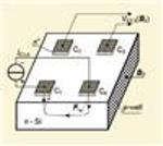 BAS 3-D silicon four-contact Hall device
Patent protection is available for the new device and technique. This innovation has various practical applications that include antiterrorist activities, low-field magnetometry for detecting the earth magnetic field’s perturbations and variations, health, nanotechnologies, and atomic-force microscopy for fluids having magnetic nano-particles like blood plasma and blood.
The BAS team has expanded the measurement process in time but not in space. In a subsequent process the same device is utilized with the same transducer region though at a different time. By ensuring a high enough measurement repetition frequency and short enough interval registration, it will be possible to achieve negligible changes in Bx, By and Bz component values.
The new 3-D microsensor has a square n-Si structure along with four n+-contacts. These C1, C2, C3 and C4 contacts are placed at the top surface, in the vicinity of the four corners. The active transducer zone’s isolation from the rest of the substrate is ensured by using lateral deep p-well.
BAS has explained the new multisensor device’s operating principle. The in-plane Bx measurement utilizes IC1,4’s supply current. The opposite Lorentz deflections of vertical to the surface components IC1 and – IC4 generate on the contacts C2 and C3. A Hall voltage VC2,3(Bx) is generated on the C3 and C2 contacts through the opposite vertical Lorenz deflections in IC1 and IC4 surface contacts.
The next magnetic field measurement step uses the IC1,2, while VC3,4(By) is the Hall voltage). The By sensor operation is similar to that of the Bx. The Lorentz deflections are vertical to IC1 and IC2, current components at the top surface which are in opposite directions. This results in generation of Hall voltage VC3,4(By) on C3 and C4 contacts. In the last step realizes the Bz measurement is realized by current IC1,3, with the output voltage VC2,4(Bz) between electrodes C2 and C4 electrodes.