Columbia’s Strain Sensors are more accurate than previous, less accurate counting accelerometer systems when it comes to measuring fatigue loading encountered by aircraft under varied circumstances of speed, weight and mission design.
These sensors enable more precise monitoring of important undercarriage components and surfaces for potential fatigue damage caused by thousands of flying hours, high-stress maneuvers and landings. These sensors are also appropriate for normal laboratory applications due to their simplicity and dependability.
The Series DT3625 sensors were created in response to the demand for fatigue measurements in confined locations, and they provide the same accuracy, robustness and convenience of installation as the flight-qualified Series DTD2684 sensors.
Models for compensating materials typically utilized in aircraft structural production are available. The Columbia Model 5802 Strain Gage Amplifier is used to boost sensor readings and provide strain and temperature outputs.
Note: Exports from the United States are subject to the Export Administration Regulations (EAR) and/or the International Traffic in Arms Regulations (ITAR) authorization procedures.
- High Output — Two Active Arms
- Self-Temperature Compensating
- Ease of Installation
- Smallest Size
Specifications
Operational
Table 1. Source: Columbia Research Laboratories, Inc.
| Operational1 |
Series DT3625 |
| Operating Range (Repetitive) |
±3000 μϵ, 100 Cycles
±2000 μϵ, 10,000 Cycles |
| Input Resistance |
1000 Ω, ±2% |
| Sensitivity |
1,025 mV/V/1000 μϵ Nominal |
| Rated Excitation Voltage |
10.0 VDC |
| Linearity |
±0.75% Full Scale Maximum |
| Zero Offset |
±0.5 mV/V Typical |
| Output Resistance |
1000 Ω, ±2% |
| Hysteresis & Repeatability |
±0.5% Maximum |
| Zero Shift |
±0.005 mV/V/°F Maximum |
| Creep |
Less than 0.5%, 5 Minutes @ 2000 μϵ |
| Sensitivity vs. Temperature |
0.05%/°F Maximum |
Environmental
Table 2. Source: Columbia Research Laboratories, Inc.
| Environmental 2 |
Series DT3625 |
| Temperature Range |
-55° to +125 °C |
| Vibration |
30 g, 10 Hz to 2 KHz |
| Humidity |
MIL-STD-202 Method 103B |
| Salt Spray |
MIL-STD-202 Method 101D (168 Hours) |
| Insulation Resistance |
100 MΩ Minimum @ 500 VDC |
| Dielectric Strength |
1050 VRMS, 60 Hz, 1 Minimum |
| Altitude |
Sea Level to 70,000 Ft. |
| Shock |
100 g, 11 mSec |
| Flammability |
MIL-STD-202 Method 111A |
| Fluids |
Resistance to short term exposure to fuel, lubricating oils and hydraulic fluids |
Physical
Table 3. Source: Columbia Research Laboratories, Inc.
| Physical |
Series DT3625 |
| Size |
0.450" x 0.250" x 0.140” Thick |
| Encapsulation |
Silicone Rubber per MIL-S-23586A Type I, Class 2, Grade A |
| Weight |
Approx. 13 gms (Depending on the length of the leads) |
| Matrix |
0.001" Polyimide |
| Leads |
#26AWG, Teflon Ins, SPC, 12" Minimum |
1 @25 °C 2 Installed Gage
Schematic Diagram
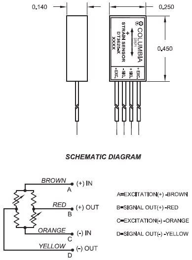
Image Credit: Columbia Research Laboratories, Inc.
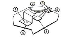
Typical Installation of Old Style Strain Gages. 1. Bolt or rivet removed from assembly; 2. Dummy gage(s) bonded to “Z Tab” of same material as structure; 3. Active gage bonded to structure under test; 4. “Z Tab” mounted to structure with bond or rivet; 5. Strain gage leads interwired and soldered to junction block; and 6. Entire unit covered with protective material. Image Credit: Columbia Research Laboratories, Inc.
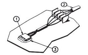
Installation of Columbia Strain Sensor. 1. Strain Sensor bonded to surface under test; 2. Leads connected to wire harness; and 3. Coat sensor and wires with waterproofing material. Image Credit: Columbia Research Laboratories, Inc.
Ordering Information
Table 4. Source: Columbia Research Laboratories, Inc.
| Model |
Lead Length |
Compensating Material |
| DT3625-1 |
48" |
Aluminum 7075-T6 or7050-T73651, IVD |
| DT3625-2 |
48" |
Steel, AISI 4130 or HP9-4-.20 |
| DT3625-3 |
48" |
Titanium TI-6AL-4V, B Annealed |
| DT3625-4 |
48" |
Carbon/Epoxy MMS 549 Type 1 |
| DT3625-5 |
48" |
Steel, Aermet 100 |
| DT3625-6 |
48" |
Copper Alloy C110 |
Advantages
- Twice as much output
- A higher level of precision
- No compromise on structural integrity
- Installation time is reduced
- Optimal temperature compensation