When the axis of primary strain is identified, Columbia Series DT 3617 Strain Sensors are designed to measure planar shear strain forces. Each sensor is a comprehensive, compact and simple-to-install gadget that uses the Columbia DTD 2684 Series Fatigue Monitoring Sensors’ established technology.
Two 1000Ω precision strain gage grids are positioned orthogonally on a one mil polyimide substrate, plus a matched set of 1000 Ω bridge completion components make up the DT 3617 Shear Strain Sensor. The complete gage is constructed in a tough, molded silicone rubber housing with four M22759 26-gauge TFE Insulated aviation lead wires.
The sensor’s bottom surface is a polyimide substrate for active strain gage components, which is pre-processed before being bonded to the test structure. The sensor’s top surface comprises axis identification marking to help in aligning the gage with the principal strain axis.
Individual models for compensating materials typically used in airplane structural production are offered. The Columbia Model 5802 Strain Gage Amplifier is used to boost sensor readings and provide strain and temperature outputs.
Note: Exports from the United States are subject to the Export Administration Regulations (EAR) and/or the International Traffic in Arms Regulations (ITAR) authorization procedures.
- Two 1000 Ω Precision Strain Gage Grids
- 90° Rosette Gage
- Rugged Construction
- Self-Temperature Compensating
Specifications
Operational
Table 1. Source: Columbia Research Laboratories, Inc.
| Operational 1 |
Series DT3617 |
| Operating Range (Repetitive) |
±3500 μϵ, 100 Cycles
±2000 μϵ, 100,000 Cycles |
| DC Resistance |
1000 Ω ±2% |
| Gage Factor (GF) |
2.05 Nominal |
| Rated Excitation |
10.0 VDC |
| Working Range |
±2000 μϵ |
| Null Offset2(Ez) |
0.5 Mv/V Maximum |
| Linearity |
±0.75% Full Scale Maximum |
| Hysteresis, Repeatability |
±0.5% |
| GF Temp. Coeff. |
±0.02%/°C |
| EzTemp. Coeff. |
0.0005 mV/V/°C |
Environmental
Table 2. Source: Columbia Research Laboratories, Inc.
| Environmental 3 |
Series DT3617 |
| Temperature Range |
-55° to +125 °C |
| Vibration |
30 g, 10 Hz to 2 KHz |
| Humidity |
MIL-STD-202 Method 110A |
| Salt Spray |
MIL-STD-202 Method 101D (168 Hours) |
| Insulation Resistance |
100 MΩ Minimum @ 500 VDC |
| Dielectric Strength |
500 VRMS, 60 Hz, 1 Minimum |
| Altitude |
Sea Level to 70,000 Ft. |
| Shock |
100 g, 11 mSec |
| Flammability |
MIL-STD-202 Method 111A |
| Fluids |
Resistance to short term exposure to fuel, lubricating oils and hydraulic fluids |
Physical
Table 3. Source: Columbia Research Laboratories, Inc.
| Phical |
Series DT3617 |
| Size |
0.560" x 0.560" x 0.150" Thick |
| Encapsulation |
Silicone Rubber per MIL-S-23586A Type I, Class 2, Grade A |
| Weight |
Approx. 13 gms (Depending on the length of the leads) |
| Matrix |
0.001" Polyimide |
| Leads |
#26AWG, Teflon Ins, SPC, 12" Minimum |
1 @25 °C 2 As supplied (un-mounted) 3Installed Gage
Schematic Diagram
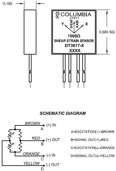
Image Credit: Columbia Research Laboratories, Inc.

Typical Installation of Old Style Strain Gages. 1. Bolt or rivet removed from assembly; 2. Dummy gage(s) bonded to “Z Tab” of same material as structure; 3. Active gage bonded to structure under test; 4. “Z Tab” mounted to structure with bond or rivet; 5. Strain gage leads interwired and soldered to junction block; and 6. Entire unit covered with protective material. Image Credit: Columbia Research Laboratories, Inc.

Installation of Columbia Strain Sensor. 1. Strain Sensor bonded to surface under test; 2. Leads connected to wire harness; and 3. Coat sensor and wires with waterproofing material. Image Credit: Columbia Research Laboratories, Inc.
Ordering Information
Table 4. Source: Columbia Research Laboratories, Inc.
| Model |
Lead Length |
Compensating Material |
| DT3617-1 |
24" |
Aluminum 7075-T6 or 7050-T73651, IVD |
| DT3617-2 |
24" |
Steel, AISI 4130 or HP9-4-.20 |
| DT3617-3 |
24" |
Titanium TI-6AL-4V, Annealed |
| DT3617-4 |
24" |
Carbon/Epoxy MMS 549 Type 1 |
Advantages
- Twice as much output
- A higher level of precision
- No compromise on structural integrity
- Installation time is reduced
- Optimal temperature compensation