Aug 10 2012
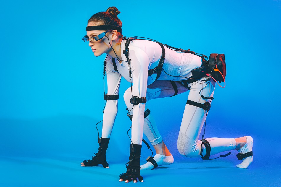
Image Credit: Mark Agnor/Shtterstock.com
If you have ever seen The Lord of the Rings film trilogy (2001 to 2003) then you’ll certainly remember the gaunt fictional character Gollum. This was one of the most difficult characters to bring to life for the trilogy, but was made possible using motion capture sensor technology.
The animation of a fictional character, like Gollum on-screen, demonstrates how effective motion capture sensor systems can be:
Motion capture or motion-tracking systems record the movement of an object or person. The system is so sophisticated, it requires a certain number of capture sessions where the movement of an object is recorded multiple times per second. The data on the object’s movement is mapped out into a 3D model. The model mirrors the exact movement positions as the object that is wired to the motion sensor network.
The following flowchart illustrates the different types of motion sensors:
.bmp)
Optical motion sensors capture the image data and triangulate the 3D positioning of an object using multiple cameras at varying angles. The markers attached to the object make this positioning possible. The markers (i.e., the motion sensors) are attached to the surface of the object being captured. Passive markers are coated with a retro-reflective material that can reflect the light source. This technique is important for ensuring that only movement is tracked. Software is integrated to help model the 3D image after receiving data on the movement of the object. With character Gollum, the actor creating the movement was dressed in a suit attached to reflective markers. The video cameras recording the actor’s movements for a particular scene in the film, captured the motion data from several different angles. This allowed the software to monitor the movement of the markers on the actor and to use this data to program sliders (camera movement system) to help animate the character.
With active marker systems, the sensor (marker) light source, often an LED, emits an electromagnetic field that is detected in real-time. Yet, the large amount of wiring involved could stop the subject from performing intricate movement.
Non-Optical Motion Capture Systems
Non-optical systems for motion capture are split into three different types of sensors:
- Inertial sensors
- Mechanical motion sensors
- Magnetic sensors
Inertial Motion Sensors
Measurement sensors such as accelerometers and gyroscopes are commonly applied for motion tracking. The motion data from these sensors is detected and recorded by a computer software system. Tracking movement using inertial sensors can be difficult as the data recorded can be ambiguous. Therefore, creating models of human motion was a prerequisite for obtaining the most accurate readings on human movement.
The combination of both accelerometers and gyroscopes to measure movement is controlled through an algorithm. The gyroscope in this motion sensor network measures the orientation of the sensor data that reflects gravitational acceleration. By subtracting the gravitational acceleration from the sensor frame, the accelerometer can calculate the initial position.
Mechanical Motion Capture Sensors
A mechanical motion capture system is a structure that is attached to the subject to act out a sequence of movements. Typically, a mechanical motion system consists of electrogoniometers – a sensor system made up of potentiometers or transducer technology. It estimates joint angles when positioned close to a joint on the subject’s body. Compared to inertial sensors, the mechanical motion capture system allows for direct measurement of movement, meaning that the subject can move around more freely in a large environment without any movement being out of view by a central camera system, nor is the capture system affected by reflective light. A wireless mechanical motion sensor system can enhance the capture volume.
A good example of a wireless mechanical motion capture sensory system is the Gypsy 5 engineered by Meta Motion and has a half-a-mile range. The mechanical motion system may give the subject more freedom to move around in a larger space, but it limits the subject’s degrees of freedom and the positioning of sensors on the attached mechanical system. The following video by Inition, a 3D technology, and production company, presents a GypsyGyro18 demo of a mechanical motion capture system in use. The system does not require extensive calibration yet still delivers clean data on subject movements.
Magnetic Motion Sensors
This type of motion capture sensor calculates a low-frequency magnetic field created by a transmitter. The magnetic current is detected by orthogonal coils in the transmitter. There are two types of magnetic current flows: the direct current (DC) technique and the alternating current (AC) system. With the DC system, the magnetic current flows in the form of square pulse waves; contrary, sine pulse waves are generated with an AC current.
A magnetic motion system involves using 6–11 sensors around the joint of the subject’s body, which work to produce measurements on the position and rotation of the corresponding joint. The accuracy of position measurements is reduced by the simultaneous performance of multiple magnetic systems. The distortion of results is due to interfering sensors from opposing magnetic capture systems.
This capture system can react to magnetic fields in the surrounding environment which interferes with the magnetic current flow generated by the transmitters and receivers on the subject; hence why this type of capture system is better used in controlled environments. Unlike the mechanical capture system that has a limited degree of freedom, the magnetic motion capture setup is built with transmitters allowing for up to six degrees of freedom (including roll orientation angle measurements), which offers the subject more movement creativity.
The military is widely known for using magnetic motion capture systems for head tracking. In this context, the system is used to calculate the pilot’s line of sight so that weapons are released with maximum accuracy. Further application of magnetic motion sensors is in the medical industry where such systems are engineered to measure organ size inside the human body – particularly useful during surgical procedures to allow for better accuracy.
Sources and Further Reading
This article was updated on 14th February, 2020.